Buttons and joystick
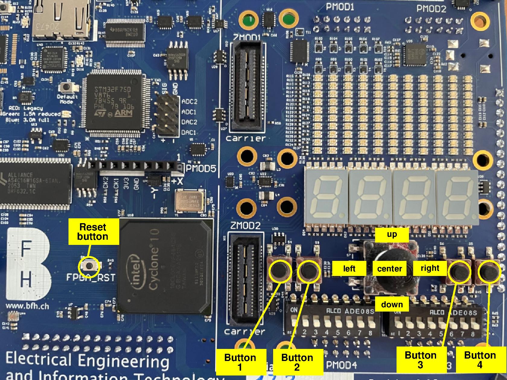
The leguan provides five push-buttons and a digital joystick:
Important
All the buttons and the joystick signals are active low, meaning that when activating them they will provide a logic level 0, and when they are not activated, they give a logic level 1. Furthermore, some of them have external pull-up resistors, and some of them require an FPGA-IOB pull-up resistor to function correctly!
Buttons
The leguan board provides five general purpose buttons. Although the reset button is marked specially, it’s functionality is not different from the other four.
The table below shows the pins on which they are connected on the FPGA, and if they require an FPGA-IOB pull-up resistor:
Name: |
FPGA pin: |
requires pull-up: |
|---|---|---|
Reset button |
PIN_A11 |
No |
Button 1 |
PIN_T2 |
No |
Button 2 |
PIN_V3 |
Yes |
Button 3 |
PIN_T21 |
No |
Button 4 |
PIN_T1 |
No |
Below you find the snippets on how to use these buttons in your toplevel.
Note
Except from button 2 all are connected to clock-input-pins of the FPGA. They can hence also be used as clock source.
Joystick
The table below shows the pins on which the joystick is connected on the FPGA and if the connections requires an FPGA-IOB pull-up resistor:
Name: |
FPGA pin: |
requires pull-up: |
|---|---|---|
up |
PIN_W2 |
Yes |
down |
PIN_E9 |
Yes |
left |
PIN_W1 |
Yes |
right |
PIN_G8 |
Yes |
center |
PIN_G11 |
Yes |
Below you find the snippets on how to use these buttons in your toplevel.
Using the buttons and/or joystick
In this section you find a VHDL top-level entity and the corresponding tcl-file that you can use to use the button(s) and/or joystick.
Important
Although VHDL is case-insensitive, the tcl-files are not. Meaning that the port-names in the top-level entity need to be copied exactly in the tcl-files.
An example for a VHDL top-level entity is shown below:
library ieee;
use ieee.std_logic_1164.all;

entity leguanToplevel is
  port ( button1_b        : in std_logic;
         joystickCenter_b : in std_logic );
end leguanToplevel;
To connect the above ports to the correct pins of the FPGA, following tcl-script can be used:
set_location_assignment PIN_T2 -to button1_b
set_location_assignment PIN_G11 -to joystickCenter_b

set_instance_assignment -name WEAK_PULL_UP_RESISTOR ON -to joystickCenter_b
Note
The suffix
_bto the port names. This is general practice to indicate an active-low signal.The
set_instance_assignment -name WEAK_PULL_UP_RESISTOR ON -to joystickCenter_bline in the tcl-script. This instructs quartus to activate the FPGA pull-up resistor in the IOB. If this line would be omitted, thejoystickCenter_bdoes not function. The reason for this is that in case the center of the joystick is not activated, the input is floating.As
button1_bdoes not require an FPGA IOB pull-up resistor, you must not specify aset_instance_assignment -name WEAK_PULL_UP_RESISTOR ON ....for this signal in the tcl-file!
Hint
To activate the assignments, following steps need to be taken in quartus:
Go to
Tools->Tcl scripts....Add the
tclscript to your project by pressing the ButtonAdd to Project....Highlight the
tclscript by clicking on it in theLibraries:window.Press the
Runbutton.