Oscilloscope
First, a general overview of the Oscilloscope is given, in which the single parameters are described. Afterwards the technical principle of the implementation is explained. At the end, some limitations and some ideas for future development are listed.
Quick Specs
The input channels of the oscilloscope are in the middle of the Leguan board, as shown in the following image:
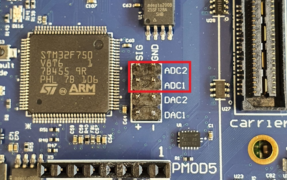
The inputs are sampled with 500 kHz and the input voltage can only range from 0VDC to 3.3VDC.
Overview
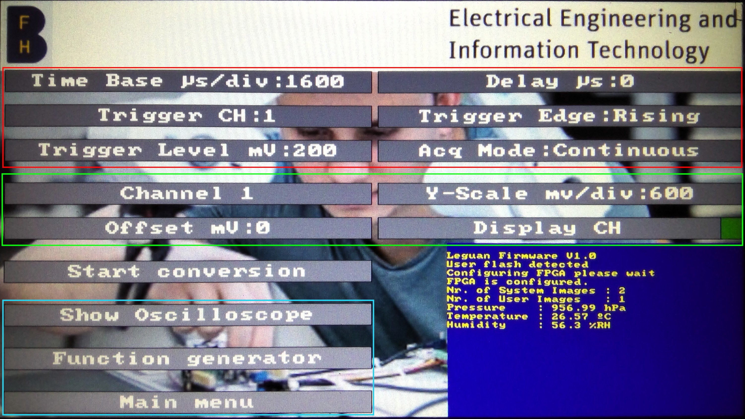
The oscilloscope consists of two different screens. One is showing the actual oscilloscope screen and the other screen is for adjusting the parameters.
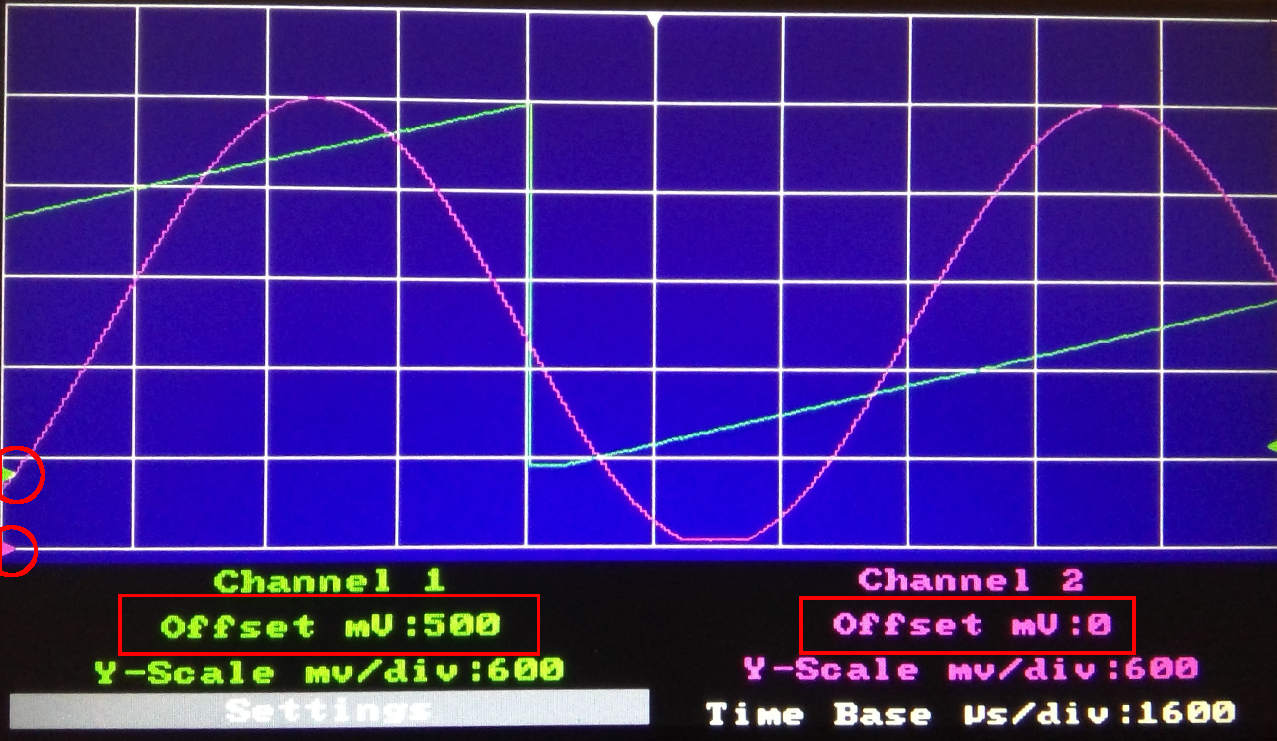
This two channel oscilloscope has multiple adjustable parameters. The user can set the parameters with the help of the GUI. The corresponding menu is located in the main menu under the “Waveforms” menu item. Some of the parameters are affecting the complete oscilloscope (red) others are channel specific (green).
Marked in blue are navigation elements. They can be used for displaying the oscillosocpe screen or navigating to the function generator or main menu .
Following, the single parameters and the valid inputs are described. In sections describing a numerical parameter, a table shows the valid range of the parameter, which can be entered in the GUI.
Time Base
The time base is the scale of the X-axis of the display. It is directly linked to the sampling rate of the ADC, since what is displayed on the oscilloscope screen are samples. In the current system the sampling rate is fixed (see Known Issues and Limitations. So the only way to change the time base is by skipping the samples to be displayed.
The macro TIMEPERSAMPLE_US, defined in “oscilloscope.h”, defines the amount of µs between two samples, which corresponds to the sampling period. The macros MINTIMEBASESAMPLES (1) and MAXTIMEBASESAMPLES (20), defined in the same file, are describing the range of the time base in terms of the samples to be skipped. The maximum value is limited by the size of the sample buffer (OSCIBUFFERSIZE), the screen width and the time delay.
By multiplying the TIMEPERSAMPLE_US with the size of one division (gridCol[1]-gridCol[0]) of the oscilloscope display, the time base expressed in can be obtained. Which is also the unit in which the user has to input the parameter.
| Formula | Minimum | Maximum |
|---|---|---|
The table above shows the formula for calculating the time base in . The only value which is changing during runtime is TIMEBASESAMPLES. Consequently the time base can only be a multiple of:
If the user enters a value which is not a multiple as shown above, the time base becomes the closest valid value. If the input is less or greater than the maximum value shown in the table above, the old value is kept.
The time base is also displayed in the oscilloscope screen and not only in the settings screen.
This parameter affects both oscilloscope channels.
Delay
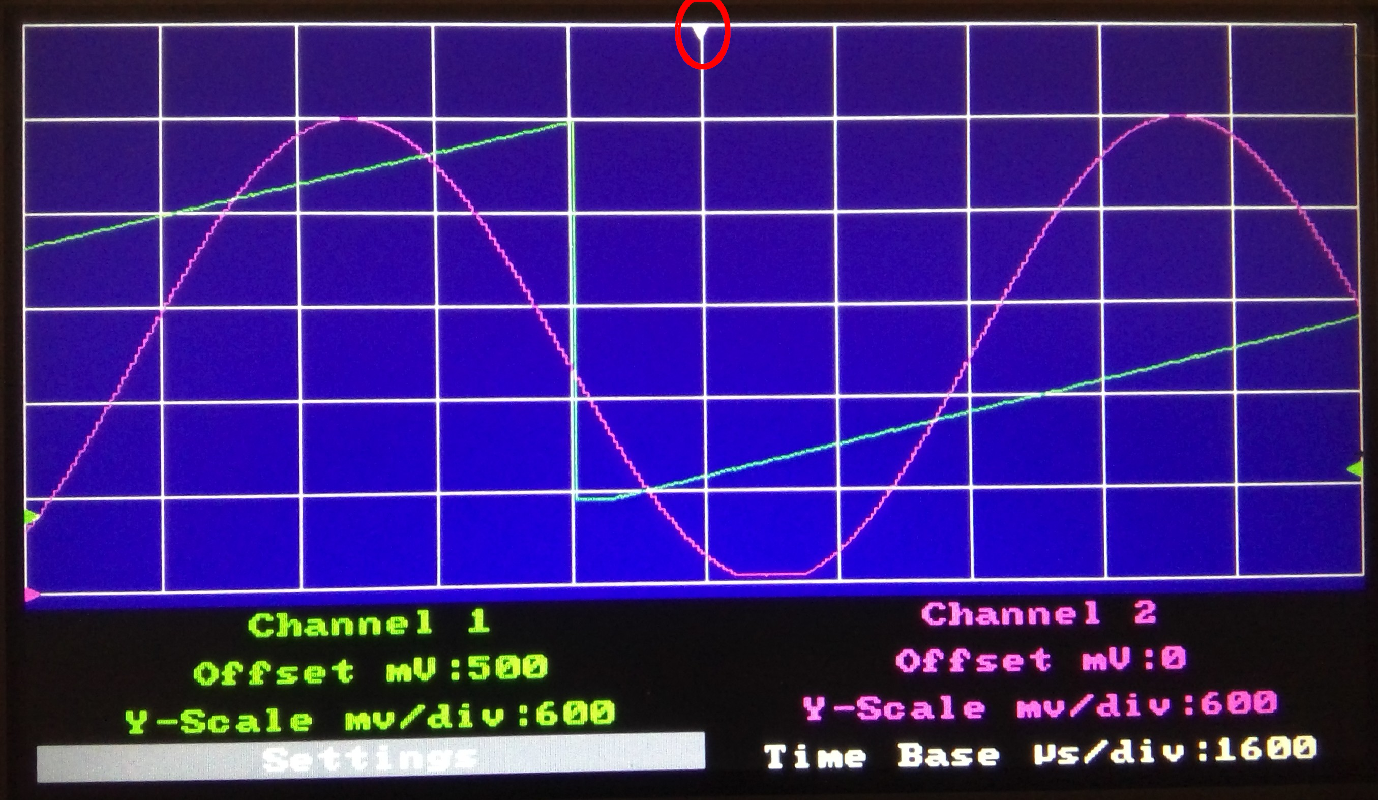
Normally the middle of the oscilloscope screen in the X-axis shows the moment of the trigger condition. With the delay parameter a time delay is implemented, which moves the moment of the trigger on the screen. This delay is expressed in µs and can be positive (rigtht) or negative (left). The time delay, and consequently the trigger moment, is indicated with a white arrow located at the top of the oscilloscope screen.
Again, time corresponds to samples. While the user enters the value in µs, the actual offset must be calculated in samples. This is easily achieved by dividing the entered value by the macro TIMEPERSAMPLE_US. Hence the time delay can only be a multiple of TIMEPERSAMPLE_US.
The minimum and maximum value (MAXTIMEOFFSETSAMPLES) of this parameter, expressed in samples, is currently a quarter of of the sample buffer (OSCIBUFFERSIZE) size. By multiplying the extremes by TIMEPERSAMPLE_US, the extremes expressed in µs can be calculated. Currently the input of the numpad is limited to which is here limiting the maximum and minimum of this parameter.
Minimum and maximum value for time delay:
| Minimum | Maximum |
|---|---|
-MAXTIMEOFFSETSAMPLES respectively |
MAXTIMEOFFSETSAMPLES respectively |
This parameter affects both oscilloscope channels.
Trigger channel
This parameter defines, which channel buffer is examined for a trigger condition. Can be either Channel 1 or Channel 2.
Trigger edge
This parameter defines, whether the trigger channel is searched for a rising or falling edge of the signal.
Trigger level
The threshold for the trigger. This threshold must be exceeded (rising edge) or undershot (falling edge) for triggering the oscilloscope. The maximum value is defined by the maximum input voltage processed by the ADC, which is 3.3 Volt. To simplify processing the value must be entered in .
Minimum and maximum values for the trigger level:
| Minimum | Maximum |
|---|---|
MAXTRIGGERLVL () |
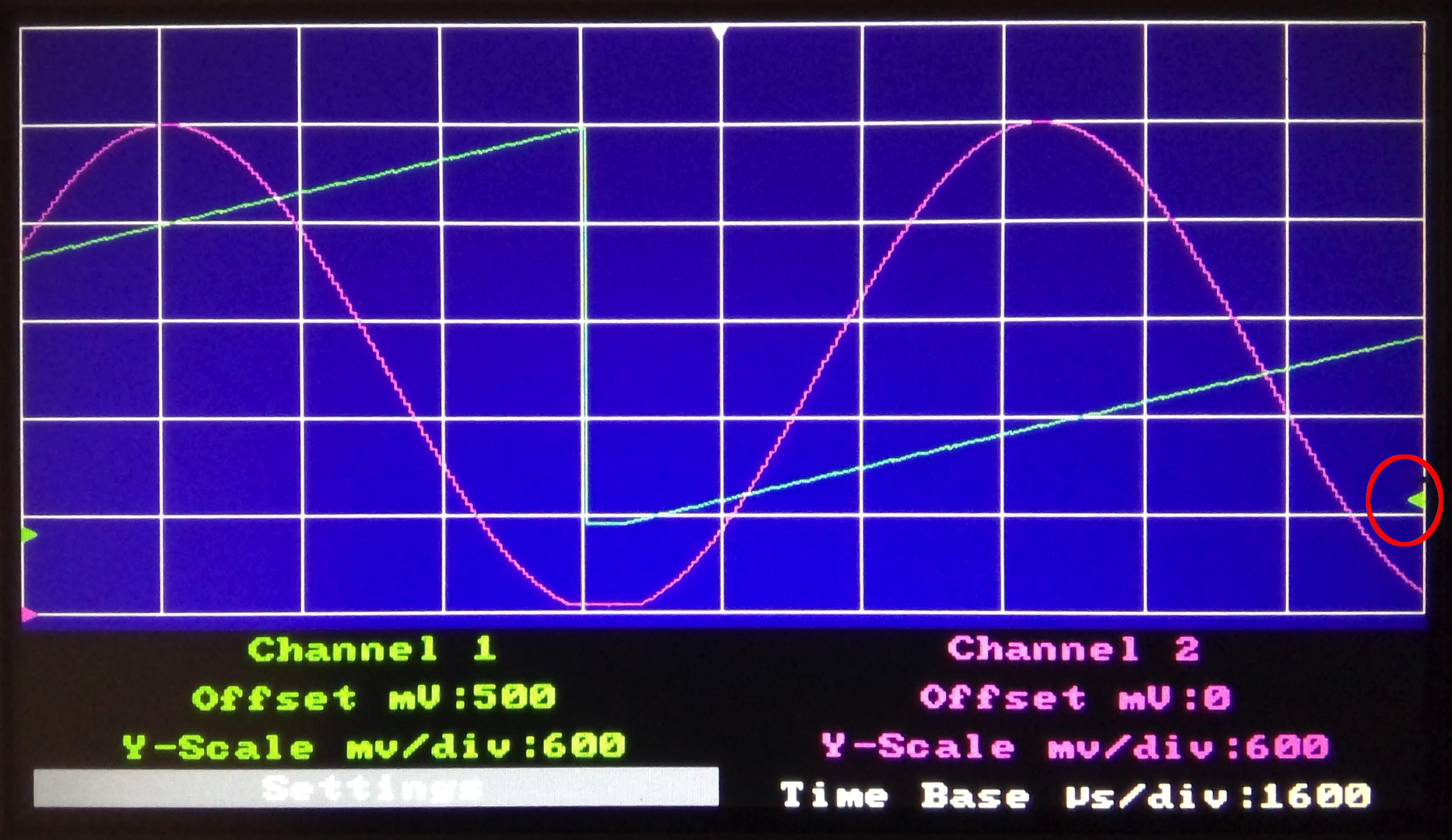
The trigger level is visible in the oscilloscope screen. It is represented by an arrow on the right side of the screen. Its colour corresponds to the colour of the trigger channel (CH1COLOUR or CH2COLOUR).
The screen is only drawn if a trigger condition was detected.
Acquisition mode
This oscilloscope knows two different acquisition modes: Single acquisition and continuous acquisition.
In single acquisition mode, the ADC is sampling, as long no trigger is detected. If a trigger was detected, the acquisition is stopped and the screen is drawn. Until a new acquisition is started manually, by pressing the “Start conversion” button, and no trigger was detected, the screen remains the same.
In continuous acquisition mode, a new ADC conversion is started, as soon as the screen was drawn. A new screen is drawn, whenever a trigger was detected.
Channel
Defines whether channel one or two should be adjusted. Channel specific parameters are Y-Scale, Offset and Display channel.
Y-scale
This parameter is used for adjusting the Y-scale of each channel separately. This value must be entered in by the user. The minimum (MIN_MV_DIV) and maximum (MAX_MV_DIV) values for this parameters are defined in the “oscilloscope.h” file.
Y-Scale maximum and minimum values:
| Minimum | Maximum |
|---|---|
MIN_MV_DIV () |
MAX_MV_DIV () |
This parameter affects the conversion factor mVToPixel, which is used for converting a value in to a value representing a pixel in the Y-Scale. This value is defined for each channel separately.
This parameter is displayed in the oscilloscope screen too and not only in the settings screen.
Offset
This parameter is an offset in the Y-axis, hence it corresponds to a value in . When displaying the signal, this value is added to the signal, so the signal is displayed higher than its actual value. The maximum value for this parameter is defined with the macro MAXOSCIOFFSET.
Channel offset maximum and minimum values:
| Minimum | Maximum |
|---|---|
MAXOSCIOFFSET () |
This parameter affects only the current selected channel. The channel offset is displayed also in the oscilloscope screen and not only in the settings screen. In the oscilloscope screen, it is displayed in two different ways. Once it is displayed as a label and once as an arrow on the left side of the screen. Both times the colour is the same as the displaying colour of the signal.
Display channel
Defines whether a channel is displayed or not. In the GUI this is represented by a checkbox.
Working principle
Data structures
The core element of the oscilloscope is the oscilloscope structure, which is defined in the header file “oscilloscope.h”. The structure contains one element for each parameter that affects both channels. The channel specific parameters are grouped in another structure called osciChannel, which is defined in the same file. Consequently, the “Oscilloscope” structure has two members of the “OsciChannel” structure, each representing one channel. These parameters are changed by using the GUI and the corresponding setter functions. The “Oscilloscope” structure also contains several control flags and labels that are used for display purposes.
The oscilloscope structure:
typedef struct oscilloscope {
	uint32_t valueBuf[OSCIBUFFERSIZE];  ///< Buffer where ADC stores sampled data of both ADC channels
	fxpt_16_16 ADC_to_mV;               ///< Conversion factor for ADC value (12 Bit) to mV conversion. Fixed point representation for efficient calculations. @note Fixed point representation! @see fxpt_16_16
	fxpt_16_16 triggerLevel_Pixel;      ///< Trigger Level in terms of pixel. Used for displaing the trigger level. Fixed point representation for efficient calculations. @note Fixed point representation! @see fxpt_16_16
	int16_t timeOffset;                 ///< Time offset (X-Direction) in samples
	uint16_t timeBaseInSamples;         ///< Time base expressed in samples to be skipped
	uint16_t defTimePerDivUs;           ///< Default time per division  in us
	uint16_t timePerDivUs;              ///< Time per division  in us
	uint16_t triggerLevel_mV;           ///< Trigger level in mV
	int16_t triggerLocation;            ///< Trigger location index of buffer
	int8_t triggerChannel;              ///< Channel which is triggering

	bool triggerEdgeRising;             ///< Edge of trigger is rising (true) or falling
	bool convComplete;                  ///< Flag for signaling hat ADC has finished conversion
	bool continuousAcquisition;         ///< True if acquisition is continuous, false if single acquisition
	bool startAcquisiton;               ///< Flag used for starting a new conversion in single acquisition mode

	LabelInfoType CH1Label;             ///< Label displaying the channel 1 string
	LabelInfoType CH2Label;             ///< Label displaying the channel 2 string
	LabelInfoType CH1OffsetLabel;	    ///< Label displaying the offset of channel 1
	LabelInfoType CH2OffsetLabel;	    ///< Label displaying the offset of channel 2
	LabelInfoType CH1YScaleLabel;	    ///< Label displaying the Y-Scale of channel 1
	LabelInfoType CH2YScaleLabel;	    ///< Label displaying the Y-Scale of channel 2
	LabelInfoType timeBaseLabel;	    ///< Label displaying the time scale

	struct osciChannel CH1;             ///< Osci channel 1
	struct osciChannel CH2;             ///< Osci channel 2
} oscilloscope;
The oscilloscope channel structure:
typedef struct osciChannel {
	uint16_t pixelBuffer[OSCIBUFFERSIZE];	///< Buffer containing the sampled data, expressed in pixels (ready to display)
	fxpt_16_16 mVToPixel;                   ///< Conversion factor from mV to pixels, dependent on the Y-Scale. Fixed point representation for efficient calculations. @note Fixed point representation! @see fxpt_16_16
	int16_t offset;                         ///< Offset in Y direction in mV
	uint16_t mv_Div;                        ///< Y-Scale in mV/div
	bool isOn;                              ///< Displaying the channel or not
} osciChannel;
The flowchart shows the basic principle of the oscilloscope:
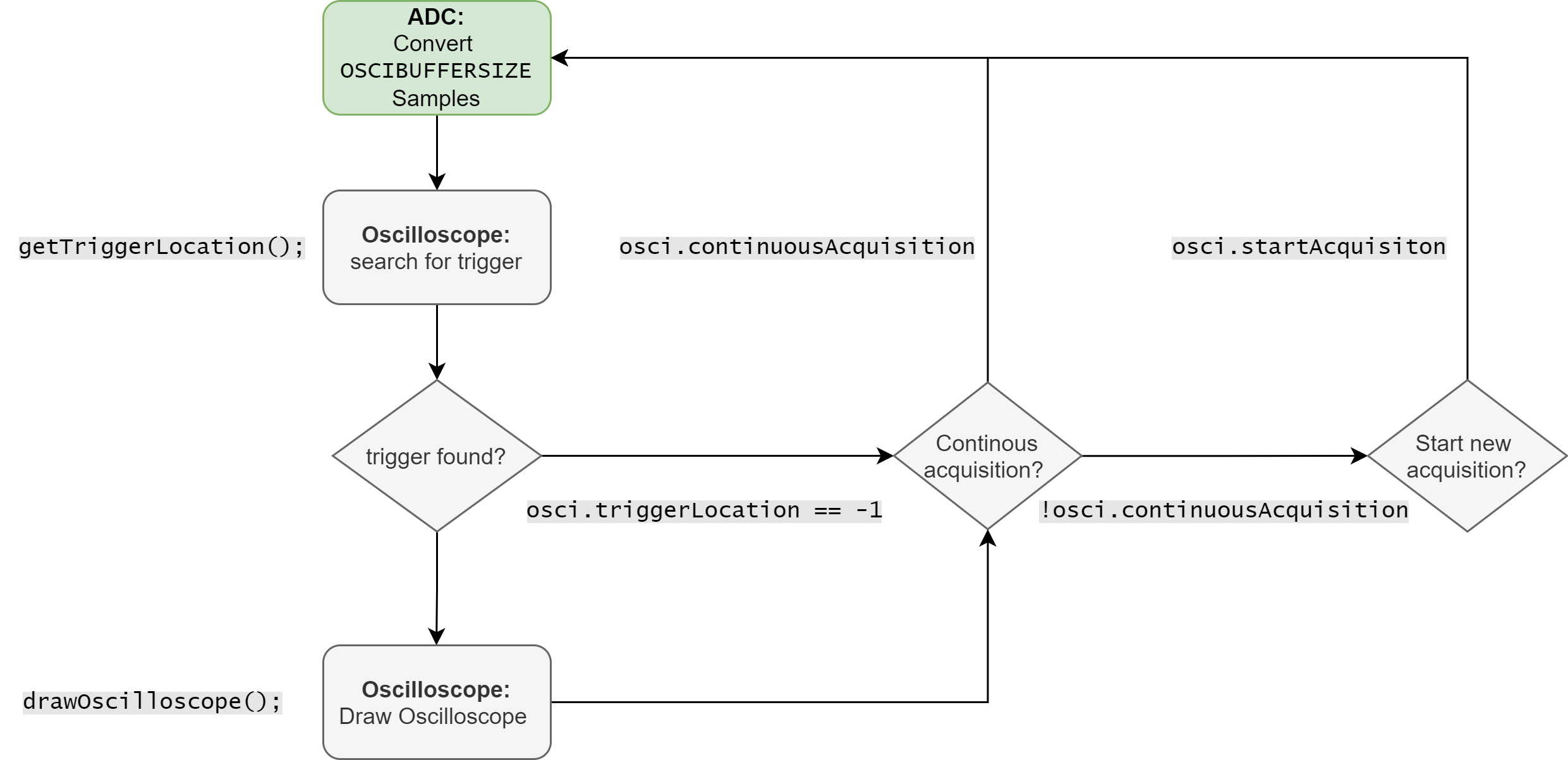
ADC
When the oscilloscope is initialised (initOscilloscope()), all structure elements are initialised. In addition, a first ADC conversion is started. The ADC conversion is performed in multimode, specifically in regular simultaneous mode (p. 433), to be precise. This means that both ADC channels are converted synchronously. At the end of each conversion, the values of both channels are transmitted via DMA in a 32-bit value. Thereby, the value stored in the lower half-word (12-bit) corresponds to ADC channel 1 and the value stored in the upper half-word corresponds to ADC channel 2. Currently, the sampling frequency is . The sampling frequency is calculated as follows:
The ADC performs OSCIBUFFERSIZE conversions before calling the callback function (HAL_ADC_ConvCpltCallback()). In this callback function, a flag of the oscilloscope structure is set indicating that the conversion is complete (convComplete).
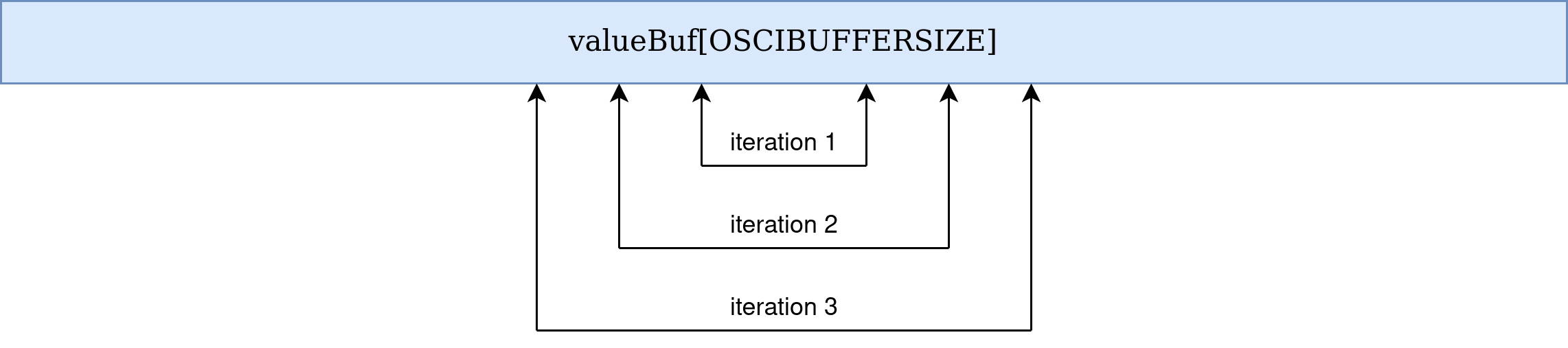
Trigger
When the oscilloscope is active and the above mentioned flag is set, the trigger channel is searched for a trigger condition (getTriggerLocation()). The search for the trigger condition starts within a small range that is in the middle of the value buffer (valueBuf[]). If no trigger was found, the range is extended with each iteration (Figure) until a trigger was found or the entire buffer was searched.
If no trigger was found, a new ADC conversion is started. If a trigger was found, the oscilloscope screen is drawn and then a new conversion is started if continuous acquisition is active. In single acquisition mode, a new conversion is only started if the start conversion key has been pressed.
Drawing
In order to draw the screen, the content of the value buffer is converted (mVToPixel) into a pixel representation for each channel (pixelBuffer[]). In this way, channel-specific parameters such as the Y-scale and the offset can be taken into account. In addition, the drawing of the display is simplified because the buffer values correspond to the Y-coordinate of the display. The area of the buffer that is actually drawn, and thus the X-coordinate of the display, is defined by the trigger position, the time base and the delay.
Known Issues and Limitations
Some known problems and limitations are described below. If possible, ideas for a potential solution to the problems are given.
Samplingrate
Currently, the sampling rate is determined by a combination of the clock prescaler (8) and the sampling time (15 cycles) of the ADC. Due to this circumstance, the number of different sampling rates is limited to the different combinations of the parameters. Furthermore, only a few combinations result in a time base that is user-friendly. Together with the fact that the sampling frequency should be chosen to cover a reasonable bandwidth, only the current combination is actually a viable choice. An attempt was made to trigger the ADC with a timer so that the sampling rate can be easily adjusted and the problem described can be solved. However, this only worked for very low timer frequencies, but not for the desired frequencies.
Future developments should therefore consider triggering the ADC with a timer.
Time delay
When adjusting the time delay, it can happen that the end of the buffer becomes visible. The problem is, of course, worsened when the time base becomes larger, because this causes a larger part of the buffer to be displayed. Another factor that reinforces this problem is when the sampled signal has a low frequency. With a periodic signal of low frequency, the trigger condition occurs less often than with high frequencies. Since the entire buffer is searched for a trigger condition, it is possible that it is found near the end of the buffer. This increases the probability of the described behaviour.
No simple solution to this problem is evident. One approach could be seamlessly sampling (see dead time) so that the trigger position is always in the “middle” of the data to be displayed. In this way, a hard limit for the time delay could be introduced so that the phenomenon no longer occurs.
Trigger detection
Sometimes the trigger is detected at the wrong edge. Currently, a sample is compared with the two following samples for trigger detection. Apparently this is not sufficient to always recognise the correct edge.
To increase the reliability of the edge detection, more samples could simply be taken into account. Alternatively, a better algorithm would have to be developed.
Dead time
After an ADC conversion, the screen is drawn and then a new conversion is started (if desired). Consequently, no ADC conversions are made between the end of the conversion and the end of the drawing, so there is currently no seamless conversion.
It would be possible to convert the data seamlessly by using two different buffers. However, due to synchronicity, a new conversion should be started by the hardware, as soon as one buffer is full. Since the currently used buffer already requires a lot of memory, the size of a single buffer would have to be reduced. The biggest challenge would probably be drawing the screen without changing the data needed for this task.
File overview
The table below shows an overview of the files and its content related to the oscilloscope.
| File | Content |
|---|---|
| Oscilloscope/oscilloscope.h | Contains all macros, typedefs and function declerations concerning the oscilloscope in general (no drawing). |
| Oscilloscope/oscilloscope.c | Implementation of the functions. |
| Oscilloscope/oscilloscopeDisplay.h | Contains all macros, typedefs and function declerations related to drawing the oscilloscope screen. |
| Oscilloscope/oscilloscopeDisplay.c | Implementation of the functions. |
| gui/osciMenu.h | Declaration of global accessible GUI functions |
| gui/osciMenu.c | Implementation of menu handling functions |
Source code documentation
Structures
-
struct osciChannel
Structure describing an oscilloscope channel.
Public Members
-
uint16_t pixelBuffer[OSCIBUFFERSIZE]
Buffer containing the sampled data, expressed in pixels (ready to display)
-
fxpt_16_16 mVToPixel
Conversion factor from mV to pixels, dependent on the Y-Scale. Fixed point representation for efficient calculations.
- See
Note
Fixed point representation!
-
int16_t offset
Offset in Y direction in mV.
-
uint16_t mv_Div
Y-Scale in mV/div.
-
bool isOn
Displaying the channel or not.
-
uint16_t pixelBuffer[OSCIBUFFERSIZE]
-
struct oscilloscope
This structure describes the complete oscilloscope. Contains two channels of type osciChannel.
- See
osciChannel
Public Members
-
uint32_t valueBuf[OSCIBUFFERSIZE]
Buffer where ADC stores sampled data of both ADC channels.
-
fxpt_16_16 ADC_to_mV
Conversion factor for ADC value (12 Bit) to mV conversion. Fixed point representation for efficient calculations.
- See
Note
Fixed point representation!
-
fxpt_16_16 triggerLevel_Pixel
Trigger Level in terms of pixel. Used for displaing the trigger level. Fixed point representation for efficient calculations.
- See
Note
Fixed point representation!
-
int16_t timeOffset
Time offset (X-Direction) in samples.
-
uint16_t timeBaseInSamples
Time base expressed in samples to be skipped.
-
uint16_t defTimePerDivUs
Default time per division in us.
-
uint16_t timePerDivUs
Time per division in us.
-
uint16_t triggerLevel_mV
Trigger level in mV.
-
int16_t triggerLocation
Trigger location index of buffer.
-
int8_t triggerChannel
Channel which is triggering.
-
bool triggerEdgeRising
Edge of trigger is rising (true) or falling.
-
bool convComplete
Flag for signaling hat ADC has finished conversion.
-
bool continuousAcquisition
True if acquisition is continuous, false if single acquisition.
-
bool startAcquisiton
Flag used for starting a new conversion in single acquisition mode.
-
LabelInfoType CH1Label
Label displaying the channel 1 string.
-
LabelInfoType CH2Label
Label displaying the channel 2 string.
-
LabelInfoType CH1OffsetLabel
Label displaying the offset of channel 1.
-
LabelInfoType CH2OffsetLabel
Label displaying the offset of channel 2.
-
LabelInfoType CH1YScaleLabel
Label displaying the Y-Scale of channel 1.
-
LabelInfoType CH2YScaleLabel
Label displaying the Y-Scale of channel 2.
-
LabelInfoType timeBaseLabel
Label displaying the time scale.
-
struct osciChannel CH1
Osci channel 1.
-
struct osciChannel CH2
Osci channel 2.
-
struct OsciInfoType
GUI control structure. Containing the settings button.
-
struct LabelInfoType
structure defining a label.
-
struct osciAdjustmentHandler
Structure for adjusting the oscilloscope parameter.
Note
TODO: This structure is actually not needed anymore, but many functions use it as an argument. So this structure could be removed and the functions could be adapted.
oscilloscope.h
Defines
-
OSCIBUFFERSIZE
Amount of samples converted each time a conversion is started.
-
NSHIFT
Shift amount for the fxpt_16_16 representation.
-
MAXOSCIOFFSET
Maximum Y-scale offset in mV.
-
MAX_MV_DIV
Maximum Y-Scale value.
-
MAXISON
Maximum value for displaying the channel.
-
MAXTIMEOFFSETSAMPLES
Maximum time offset in terms of samples.
-
MAXTIMEBASESAMPLES
Maximum time base expressed in amount of samples skipped.
-
MAXTRIGGERCHANNEL
Maximum channel.
-
MAXTRIGGERLVL
Maximum level for triggering in mV.
-
MAXTRIGGEREDGE
Maximum value for setting the trigger edge.
-
MIN_MV_DIV
Minimum Y-Scale in mV.
-
MINCHANNEL
Minimum value for selecting the trigger channel.
-
MINTIMEBASESAMPLES
Minimum timebase in samples skipped.
-
TIMEPERSAMPLE_US
Controlled by clock divider and sampling time of ADC: fADC=PCLK2/(clock divider), fs = fADC/(sampling cycles + 12)
Typedefs
-
typedef int32_t fxpt_16_16
Q16.16 fixed-point type.
-
typedef struct osciChannel osciChannel
Structure describing an oscilloscope channel.
-
typedef struct oscilloscope oscilloscope
This structure describes the complete oscilloscope. Contains two channels of type osciChannel.
- See
osciChannel
-
typedef struct osciAdjustmentHandler osciAdjustmentHandler
Structure for adjusting the oscilloscope parameter.
Note
TODO: This structure is actually not needed anymore, but many functions use it as an argument. So this structure could be removed and the functions could be adapted.
Enums
-
enum PARAMS
Values:
-
enumerator CHANNELOFFSET
Y-Offset (voltage)
-
enumerator MV_DIV
Y-Scale.
-
enumerator IS_ON
Displaying the channel or not.
-
enumerator TIMEOFFSET
Offset in the X-Axis.
-
enumerator TIMEBASE
X-Scale.
-
enumerator TRIGGERCHANNEL
Trigger channel.
-
enumerator TRIGGERLVL
Level of trigger.
-
enumerator EDGE
Trigger edge (rising or falling)
-
enumerator ACQMODE
Acquisition mode (single or continuous)
-
enumerator START
Start a acquisition.
-
enumerator NO_SELECTED
Counter enum.
-
enumerator CHANNELOFFSET
Functions
-
void oscilloscopeDispatcher(void)
This function is called, if the oscilloscope is active.
    If a conversion has been completed the acquired data is searched
    for a possible trigger condition. If a trigger was found, the
    oscilloscope gets drawn.
    If the acquisition mode is continuous or a new acquisition was started
    by the user, a new conversion is started.
-
void initOscilloscope(void)
Initialise oscilloscope data structure, when starting up and starts a first ADC conversion.
-
void initOsciGraphic(void)
Initialising the graphical part of the oscilloscope.
Draws the oscilloscope screen and the labels for displaying the current settings. Draws the settings buttin- See
InitStarndardButton(), InitLabel(), appendNumberToLabelText()
-
void ADCBufferToPixelBuffer(void)
Moves data, acquired from the the ADC, from the acquisition bufer (osci.valueBuf) to the pixelBuffer of each channel.
The ADC saves the converted samples (12 Bit) of both ADC-Channels into the same 32-Bit wide buffer. The values are masked and multiplied with a factor, so the values can be stored in terms of pixels. The factor (osci.CHX.mVToPixel) depends on the current Y-Scale of the channel. The Pixelbuffer is in fixed point (Q16.16) representation, so multiplication has to be made with MULT_16_16() function.
- See
MULT_16_16(), oscilloscope
-
void getTriggerLocation(void)
Searches the sampled data for trigger condition.
The search starts in the middle of the sampled data. If no trigger can be found the range of the search is increased, until a trigger was found or the whole array has been searched. Sometimes false conditions are found. To reduce this behavior, the current sample is compared with the two following samples.- Returns
-1 – No trigger Others Index of sample where trigger occurred
-
void startAdcConversion(void)
Starting a new ADC conversion.
-
void osciSetTimeBase(int16_t value)
Setter function for the timebase of the oscilloscope. The value gets verified in osciEvaluateNumExpression() function. Called from osciMenu.c.
- Parameters
value – New value.
-
void osciSetTimeOffset(int16_t value)
Setter function for the time offset of the oscilloscope. The value gets verified in osciEvaluateNumExpression() function. Called from osciMenu.c.
- Parameters
value – New value.
-
void osciSetTriggerChannel(int8_t value)
Setter function for the trigger channel of the oscilloscope. The value gets verified in osciEvaluateNumExpression() function. Called from osciMenu.c.
- Parameters
value – New value.
-
void osciSetTriggerEdge(bool value)
Setter function for the trigger edge of the oscilloscope. The value gets verified in osciEvaluateNumExpression() function. Called from osciMenu.c.
- Parameters
value – New value.
-
void osciSetTriggerLevel(uint16_t value)
Setter function for the trigger level of the oscilloscope. The value gets verified in osciEvaluateNumExpression() function. Called from osciMenu.c.
- Parameters
value – New value.
-
void osciSetAcqMode(uint8_t value)
Setter function for the acquisition mode of the oscilloscope. The value gets verified in osciEvaluateNumExpression() function. Called from osciMenu.c.
- Parameters
value – New value.
-
void osciSetMvDiv(uint16_t value, uint8_t channel)
Setter function for the Y-Scale of the oscilloscope channel. The value gets verified in osciEvaluateNumExpression() function. Called from osciMenu.c.
- Parameters
value – New value.
channel – Oscilloscope channel to adjust.
-
void osciSetCHOffset(int16_t value, uint8_t channel)
Setter function for the channel offset of the oscilloscope channel. The value gets verified in osciEvaluateNumExpression() function. Called from osciMenu.c.
- Parameters
value – New value.
channel – Oscilloscope channel to adjust.
-
void osciSetChOn(bool value, uint8_t channel)
Setter function for displaying of the oscilloscope channel. The value gets verified in osciEvaluateNumExpression() function. Called from osciMenu.c.
- Parameters
value – New value.
channel – Oscilloscope channel to adjust.
-
uint16_t osciGetTimeBase(void)
Getter function for the time base of the oscilloscope. Called from osciMenu.c.
-
int16_t osciGetTimeOffset(void)
Getter function for the time delay of the oscilloscope. Called from osciMenu.c.
-
int16_t osciGetTriggerChannel(void)
Getter function for the trigger channel of the oscilloscope. Called from osciMenu.c.
-
bool osciGetTriggerEdgeNum(void)
Getter function for the trigger edge of the oscilloscope. Called from osciMenu.c.
- Returns
0 – If rising edge
1 – If falling edge
-
uint16_t osciGetTriggerLevel(void)
Getter function for the trigger level of the oscilloscope. Called from osciMenu.c.
-
bool osciGetAcqModeNum(void)
Getter function for the acquisition mode of the oscilloscope. Called from osciMenu.c.
- Returns
0 – if continuous acquisition
1 – If single acquisition
-
uint16_t osciGetMvDiv(uint8_t channel)
Getter function for the Y-Scale of the oscilloscope channel. Called from osciMenu.c.
- Parameters
channel – Oscilloscope channel of interest.
- Returns
true – if on
-
int16_t osciGetCHOffset(uint8_t channel)
Getter function for the offset of the oscilloscope channel. Called from osciMenu.c.
- Parameters
channel – Oscilloscope channel of interest.
-
bool osciGetChOn(uint8_t channel)
Getter function for the displaying state of the oscilloscope channel. Called from osciMenu.c.
- Parameters
channel – Oscilloscope channel of interest.
- Returns
true – if on
-
void startAcquisition(void)
Starts a acquisition by setting the corresponding flag. Called from osciMenu.c. this function is necessary for encapsulation.
-
bool osciEvaluateNumExpression(int numVal, enum PARAMS param)
Evaluates if the a value is within the allowed range of the corresponding parameter.
- See
- Parameters
numVal – The value to check
param – The parameter which should be adjusted.
- Returns
True – if valid parameter
-
fxpt_16_16 MULT_16_16(fxpt_16_16 a, fxpt_16_16 b)
Fixed point multiplication.
-
fxpt_16_16 DIV_16_16(fxpt_16_16 a, fxpt_16_16 b)
Fixed point division.
-
struct osciChannel
- #include <oscilloscope.h>
Structure describing an oscilloscope channel.
Public Members
-
uint16_t pixelBuffer[OSCIBUFFERSIZE]
Buffer containing the sampled data, expressed in pixels (ready to display)
-
fxpt_16_16 mVToPixel
Conversion factor from mV to pixels, dependent on the Y-Scale. Fixed point representation for efficient calculations.
- See
Note
Fixed point representation!
-
int16_t offset
Offset in Y direction in mV.
-
uint16_t mv_Div
Y-Scale in mV/div.
-
bool isOn
Displaying the channel or not.
-
uint16_t pixelBuffer[OSCIBUFFERSIZE]
-
struct oscilloscope
- #include <oscilloscope.h>
This structure describes the complete oscilloscope. Contains two channels of type osciChannel.
- See
osciChannel
Public Members
-
uint32_t valueBuf[OSCIBUFFERSIZE]
Buffer where ADC stores sampled data of both ADC channels.
-
fxpt_16_16 ADC_to_mV
Conversion factor for ADC value (12 Bit) to mV conversion. Fixed point representation for efficient calculations.
- See
Note
Fixed point representation!
-
fxpt_16_16 triggerLevel_Pixel
Trigger Level in terms of pixel. Used for displaing the trigger level. Fixed point representation for efficient calculations.
- See
Note
Fixed point representation!
-
int16_t timeOffset
Time offset (X-Direction) in samples.
-
uint16_t timeBaseInSamples
Time base expressed in samples to be skipped.
-
uint16_t defTimePerDivUs
Default time per division in us.
-
uint16_t timePerDivUs
Time per division in us.
-
uint16_t triggerLevel_mV
Trigger level in mV.
-
int16_t triggerLocation
Trigger location index of buffer.
-
int8_t triggerChannel
Channel which is triggering.
-
bool triggerEdgeRising
Edge of trigger is rising (true) or falling.
-
bool convComplete
Flag for signaling hat ADC has finished conversion.
-
bool continuousAcquisition
True if acquisition is continuous, false if single acquisition.
-
bool startAcquisiton
Flag used for starting a new conversion in single acquisition mode.
-
LabelInfoType CH1Label
Label displaying the channel 1 string.
-
LabelInfoType CH2Label
Label displaying the channel 2 string.
-
LabelInfoType CH1OffsetLabel
Label displaying the offset of channel 1.
-
LabelInfoType CH2OffsetLabel
Label displaying the offset of channel 2.
-
LabelInfoType CH1YScaleLabel
Label displaying the Y-Scale of channel 1.
-
LabelInfoType CH2YScaleLabel
Label displaying the Y-Scale of channel 2.
-
LabelInfoType timeBaseLabel
Label displaying the time scale.
-
struct osciChannel CH1
Osci channel 1.
-
struct osciChannel CH2
Osci channel 2.
-
struct osciAdjustmentHandler
- #include <oscilloscope.h>
Structure for adjusting the oscilloscope parameter.
Note
TODO: This structure is actually not needed anymore, but many functions use it as an argument. So this structure could be removed and the functions could be adapted.
Public Members
-
uint16_t maxValue
Max value of current parameter to be adjusted.
-
uint16_t minValue
Min value of current parameter to be adjusted.
-
uint8_t channelToAdjust
Which channel to adjust.
-
enum PARAMS paramToAdjust
Which parameter to adjust.
-
bool isGeneralSetting
Is this a general or channel related setting?
-
uint16_t maxValue
oscilloscope.c
Functions
-
void oscilloscopeDispatcher(void)
This function is called, if the oscilloscope is active.
    If a conversion has been completed the acquired data is searched
    for a possible trigger condition. If a trigger was found, the
    oscilloscope gets drawn.
    If the acquisition mode is continuous or a new acquisition was started
    by the user, a new conversion is started.
-
void ADCBufferToPixelBuffer(void)
Moves data, acquired from the the ADC, from the acquisition bufer (osci.valueBuf) to the pixelBuffer of each channel.
The ADC saves the converted samples (12 Bit) of both ADC-Channels into the same 32-Bit wide buffer. The values are masked and multiplied with a factor, so the values can be stored in terms of pixels. The factor (osci.CHX.mVToPixel) depends on the current Y-Scale of the channel. The Pixelbuffer is in fixed point (Q16.16) representation, so multiplication has to be made with MULT_16_16() function.
- See
MULT_16_16(), oscilloscope
-
void getTriggerLocation(void)
Searches the sampled data for trigger condition.
The search starts in the middle of the sampled data. If no trigger can be found the range of the search is increased, until a trigger was found or the whole array has been searched. Sometimes false conditions are found. To reduce this behavior, the current sample is compared with the two following samples.- Returns
-1 – No trigger Others Index of sample where trigger occurred
-
void startAdcConversion(void)
Starting a new ADC conversion.
-
void switchToOsciMenu(void)
Callback function of Settings button in osci view. Return to osci GUI Menu.
- See
osciMenu.h
-
void initOsciGraphic(void)
Initialising the graphical part of the oscilloscope.
Draws the oscilloscope screen and the labels for displaying the current settings. Draws the settings buttin- See
InitStarndardButton(), InitLabel(), appendNumberToLabelText()
-
void initOscilloscope(void)
Initialise oscilloscope data structure, when starting up and starts a first ADC conversion.
-
bool osciEvaluateNumExpression(int numVal, enum PARAMS param)
Evaluates if the a value is within the allowed range of the corresponding parameter.
- See
- Parameters
numVal – The value to check
param – The parameter which should be adjusted.
- Returns
True – if valid parameter
-
void osciSetTimeBase(int16_t value)
Setter function for the timebase of the oscilloscope. The value gets verified in osciEvaluateNumExpression() function. Called from osciMenu.c.
- Parameters
value – New value.
-
uint16_t osciGetTimeBase(void)
Getter function for the time base of the oscilloscope. Called from osciMenu.c.
-
void osciSetTimeOffset(int16_t value)
Setter function for the time offset of the oscilloscope. The value gets verified in osciEvaluateNumExpression() function. Called from osciMenu.c.
- Parameters
value – New value.
-
int16_t osciGetTimeOffset(void)
Getter function for the time delay of the oscilloscope. Called from osciMenu.c.
-
void osciSetTriggerChannel(int8_t value)
Setter function for the trigger channel of the oscilloscope. The value gets verified in osciEvaluateNumExpression() function. Called from osciMenu.c.
- Parameters
value – New value.
-
int16_t osciGetTriggerChannel(void)
Getter function for the trigger channel of the oscilloscope. Called from osciMenu.c.
-
void osciSetTriggerEdge(bool value)
Setter function for the trigger edge of the oscilloscope. The value gets verified in osciEvaluateNumExpression() function. Called from osciMenu.c.
- Parameters
value – New value.
-
bool osciGetTriggerEdgeNum(void)
Getter function for the trigger edge of the oscilloscope. Called from osciMenu.c.
- Returns
0 – If rising edge
1 – If falling edge
-
void osciSetTriggerLevel(uint16_t value)
Setter function for the trigger level of the oscilloscope. The value gets verified in osciEvaluateNumExpression() function. Called from osciMenu.c.
- Parameters
value – New value.
-
uint16_t osciGetTriggerLevel(void)
Getter function for the trigger level of the oscilloscope. Called from osciMenu.c.
-
void osciSetAcqMode(uint8_t value)
Setter function for the acquisition mode of the oscilloscope. The value gets verified in osciEvaluateNumExpression() function. Called from osciMenu.c.
- Parameters
value – New value.
-
bool osciGetAcqModeNum(void)
Getter function for the acquisition mode of the oscilloscope. Called from osciMenu.c.
- Returns
0 – if continuous acquisition
1 – If single acquisition
-
void startAcquisition(void)
Starts a acquisition by setting the corresponding flag. Called from osciMenu.c. this function is necessary for encapsulation.
-
void osciSetMvDiv(uint16_t value, uint8_t channel)
Setter function for the Y-Scale of the oscilloscope channel. The value gets verified in osciEvaluateNumExpression() function. Called from osciMenu.c.
- Parameters
value – New value.
channel – Oscilloscope channel to adjust.
-
uint16_t osciGetMvDiv(uint8_t channel)
Getter function for the Y-Scale of the oscilloscope channel. Called from osciMenu.c.
- Parameters
channel – Oscilloscope channel of interest.
- Returns
true – if on
-
void osciSetCHOffset(int16_t value, uint8_t channel)
Setter function for the channel offset of the oscilloscope channel. The value gets verified in osciEvaluateNumExpression() function. Called from osciMenu.c.
- Parameters
value – New value.
channel – Oscilloscope channel to adjust.
-
int16_t osciGetCHOffset(uint8_t channel)
Getter function for the offset of the oscilloscope channel. Called from osciMenu.c.
- Parameters
channel – Oscilloscope channel of interest.
-
void osciSetChOn(bool value, uint8_t channel)
Setter function for displaying of the oscilloscope channel. The value gets verified in osciEvaluateNumExpression() function. Called from osciMenu.c.
- Parameters
value – New value.
channel – Oscilloscope channel to adjust.
-
bool osciGetChOn(uint8_t channel)
Getter function for the displaying state of the oscilloscope channel. Called from osciMenu.c.
- Parameters
channel – Oscilloscope channel of interest.
- Returns
true – if on
-
fxpt_16_16 MULT_16_16(fxpt_16_16 a, fxpt_16_16 b)
Fixed point multiplication.
-
fxpt_16_16 DIV_16_16(fxpt_16_16 a, fxpt_16_16 b)
Fixed point division.
-
struct OsciInfoType
GUI control structure. Containing the settings button.
Public Members
-
bool active
-
ButtonInfoType settingsButton
-
bool active
oscilloscopeDisplay.h
Defines
-
GRIDCOLOUR
Colour of the grid currently white.
-
CH1COLOUR
Colour of channel 1, currently green.
-
CH2COLOUR
Colour of channel 2 currently magenta.
-
LABELMAXCHARS
Maximum characters per label.
-
LABELHEIGHT
Height of the label.
-
LABELWIDTH
Width of label.
-
SCREENWIDTH
Screen width.
-
SCREENHEIGHT
Screen height.
Functions
-
void drawOscilloscope(void)
Draws the the screen of the oscilloscope.
            If a channel is on it is checked, if the
            current coordinate is either on the a signal,
            on the offset or trigger arrow.

            If this is true for only one channel, the pixel
            is drawn in the colour of the channel. If both
            channels fulfill the criteria, a logical OR is
            made between both colours. If no channel has a
            relation to the current pixel, it is checked, if
            the coordinate is on the display grid and
            consequently it is drawn in the grid colour. If
            none of this is the case, the pixel is drawn in
            the background colour.
-
void DrawLabel(LabelInfoType *labelInfo)
Draws the information label.
-
void InitLabel(uint16_t xpos, uint16_t ypos, int16_t txtIndex, uint16_t txtColour, uint16_t backColour, char *String, LabelInfoType *labelInfo)
Initialise the label.
- Parameters
xpos – X position of the label
ypos – Y-position of the label
txtIndex – Text index according to dictionary index
txtColour – Text colour
backColour – Background colour
String – String to display
labelInfo – Pointe to the label
-
void appendNumberToLabelText(int16_t newVal, bool lookUpString, int16_t textIndex, LabelInfoType *labelInfo)
Appends a number to the label.
- Parameters
newVal – The numeric value to append
lookUpString – Should the text from the dictionary be looked up?
textIndex – Index in the dictionary
labelInfo – The label of matter
Variables
-
static const uint16_t gridCol[] = {0, 80, 160, 240, 320, 400, 480, 560, 640, 720, 798}
Array defining the grid columns.
-
static const uint16_t gridRow[] = {0, 60, 120, 180, 240, 300, 360}
Array defining the grid rows.
-
static const uint8_t triangleToRight[9][9] = {{1, 1, 0, 0, 0, 0, 0, 0, 0}, {1, 1, 1, 1, 0, 0, 0, 0, 0}, {1, 1, 1, 1, 1, 1, 0, 0, 0}, {1, 1, 1, 1, 1, 1, 1, 1, 0}, {1, 1, 1, 1, 1, 1, 1, 1, 1}, {1, 1, 1, 1, 1, 1, 1, 1, 0}, {1, 1, 1, 1, 1, 1, 0, 0, 0}, {1, 1, 1, 1, 0, 0, 0, 0, 0}, {1, 1, 0, 0, 0, 0, 0, 0, 0}}
Array defining a arrow pointing to the right. Used for displaying channel offsets.
-
static const uint8_t triangleToLeft[9][9] = {{0, 0, 0, 0, 0, 0, 0, 1, 1}, {0, 0, 0, 0, 0, 1, 1, 1, 1}, {0, 0, 0, 1, 1, 1, 1, 1, 1}, {0, 1, 1, 1, 1, 1, 1, 1, 1}, {1, 1, 1, 1, 1, 1, 1, 1, 1}, {0, 1, 1, 1, 1, 1, 1, 1, 1}, {0, 0, 0, 1, 1, 1, 1, 1, 1}, {0, 0, 0, 0, 0, 1, 1, 1, 1}, {0, 0, 0, 0, 0, 0, 0, 1, 1}}
Array defining a arrow pointing to the left. Used for displaying trigger level.
-
static const uint8_t topDownTriangle[9][9] = {{1, 1, 1, 1, 1, 1, 1, 1, 1}, {1, 1, 1, 1, 1, 1, 1, 1, 1}, {0, 1, 1, 1, 1, 1, 1, 1, 0}, {0, 1, 1, 1, 1, 1, 1, 1, 0}, {0, 0, 1, 1, 1, 1, 1, 0, 0}, {0, 0, 1, 1, 1, 1, 1, 0, 0}, {0, 0, 0, 1, 1, 1, 0, 0, 0}, {0, 0, 0, 1, 1, 1, 0, 0, 0}, {0, 0, 0, 0, 1, 0, 0, 0, 0}}
Array defining a arrow pointing from top to bottom. Used for displaying time offset.
-
struct LabelInfoType
- #include <oscilloscopeDisplay.h>
structure defining a label.
Public Members
-
uint16_t xpos
X-Position.
-
uint16_t ypos
Y-Position.
-
uint16_t width
Width.
-
uint16_t height
Height.
-
uint16_t txtColour
Text colour.
-
uint16_t backColour
Background colour.
-
int16_t textIndex
Dictionary index.
-
bool active
Displaying label?
-
char Text[LABELMAXCHARS + 1]
Label text.
-
uint16_t xpos
oscilloscopeDisplay.c
Defines
-
TRIANGLE_SEMI_HEIGHT
Defines the size of the drawn triangle should be set according to triangleToRight, triangleToLeft, topDownTriangle.
-
TRIANGLE_WIDTH
Defines the size of the drawn triangle should be set according to triangleToRight, triangleToLeft, topDownTriangle.
Functions
-
bool isGridPixel(int x, int y)
Checks if a coordinate (x,y) is on the grid.
Checks if the handled over coordinate is on the grid. The two Grid-Arrays are checked, if an entry matches the coordinates.- Attention
To be more efficient, only even coordinates are checked, consequently the grid coordinates must be even numbers
- See
- Parameters
x – x-coordinate of display
y – y-coordinate of display
- Returns
True – if coordinate lies on grid
-
uint8_t isTimeOffsetPixel(int x, int y)
Checks if a coordinate (x,y) lies on the time offset arrow.
First the y-coordinate is checked, if it is smaller than the triangle width. Afterwards the x-coordinate is checked, if it lies on the time offset arrow.- Parameters
x – x-coordinate of display
y – y-coordinate of display
- Returns
True – if coordinate lies on time offset arrow
-
bool isOffsetPixel(int x, int y, int CH)
Checks if a coordinate (x,y) lies on the channel offset arrow.
The vertical difference between the channel offset and the y-coordinate is calculated. If it is smaller than the triangle height, the content of the triangle array is returned.- Parameters
x – x-coordinate of display
y – y-coordinate of display
CH – Channel of interest
- Returns
True – if coordinate lies on channel offset arrow
-
bool isTriggerPixel(int x, int y, int CH)
Checks if a coordinate (x,y) lies on the trigger level arrow.
The vertical difference between the trigger level and the y-coordinate is calculated. If it is smaller than the triangle height, the content of the triangle array is returned.- Parameters
x – x-coordinate of display
y – y-coordinate of display
CH – Channel of interest
- Returns
True – if coordinate lies on trigger level arrow
-
bool isSignal(int x, int y, int CH)
Checks if a coordinate (x,y) lies on the signal or if.
First the index within the value Buffer is calculated according to the coordinate, time base, time offset and trigger location. Afterwards the value of the pixel buffer at this index is compared to the y-coordinate.- Parameters
x – x-coordinate of display
y – y-coordinate of display
CH – Channel of interest
- Returns
True – if coordinate is signal of the according channel
-
void drawOscilloscope()
Draws the the screen of the oscilloscope.
            If a channel is on it is checked, if the
            current coordinate is either on the a signal,
            on the offset or trigger arrow.

            If this is true for only one channel, the pixel
            is drawn in the colour of the channel. If both
            channels fulfill the criteria, a logical OR is
            made between both colours. If no channel has a
            relation to the current pixel, it is checked, if
            the coordinate is on the display grid and
            consequently it is drawn in the grid colour. If
            none of this is the case, the pixel is drawn in
            the background colour.
-
void DrawLabel(LabelInfoType *labelInfo)
Draws the information label.
-
void InitLabel(uint16_t xpos, uint16_t ypos, int16_t txtIndex, uint16_t txtColour, uint16_t backColour, char *String, LabelInfoType *labelInfo)
Initialise the label.
- Parameters
xpos – X position of the label
ypos – Y-position of the label
txtIndex – Text index according to dictionary index
txtColour – Text colour
backColour – Background colour
String – String to display
labelInfo – Pointe to the label
-
void appendNumberToLabelText(int16_t newVal, bool lookUpString, int16_t textIndex, LabelInfoType *labelInfo)
Appends a number to the label.
- Parameters
newVal – The numeric value to append
lookUpString – Should the text from the dictionary be looked up?
textIndex – Index in the dictionary
labelInfo – The label of matter