RGB-led array
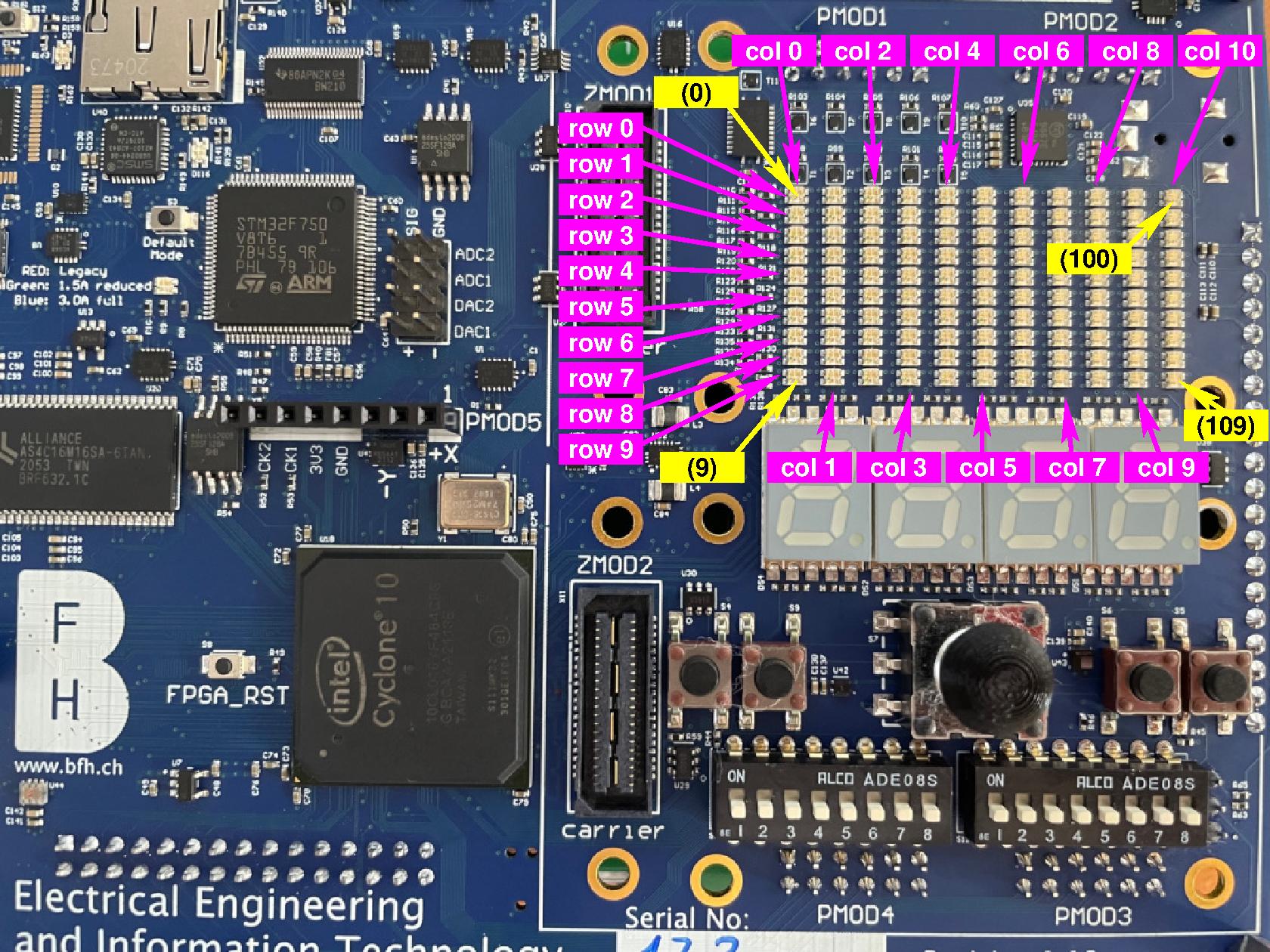
The leguan provides a RGB-led array:
Important
All the leds are active low, meaning that they will light up when a logic level 0 is provided, and that they stay off when a logic level 1 is provided!
Scanning
As connecting all RGB-led’s to the FPGA would require too much pins (11 x 10 x 3 = 330 pins), the RGB-led array is implemented by row-column selection. For this purpose there is a column address that activates a single column in the array. For the selected column the RGB-leds in each row can be activated. By selecting each column one after the other, and activating the corresponding RGB-leds in the respective rows, a scanning array can be implemented.
Column address
The column address is a four-bit vector with following selection pattern:
column address |
activated column: |
|---|---|
0000 |
col 0 |
0001 |
col 1 |
0010 |
col 2 |
0011 |
col 3 |
0100 |
col 4 |
0101 |
col 5 |
0110 |
col 6 |
0111 |
col 7 |
1000 |
col 8 |
1001 |
col 9 |
1010 |
col 10 |
others |
display off |
The table below shows the pins on which the column address is connected on the FPGA:
Name: |
FPGA pin: |
|---|---|
column address bit 0 (LSB) |
PIN_M22 |
column address bit 1 |
PIN_F21 |
column address bit 2 |
PIN_E22 |
column address bit 3 (MSB) |
PIN_E21 |
Below you find the snippets on how to use the RGB-led array in your toplevel.
Row activation
The table below shows to which FPGA pin each color in each row is connected:
Row: |
Red-led FPGA pin: |
Green-led FPGA pin: |
Blue-led FPGA pin: |
|---|---|---|---|
row 0 |
PIN_F22 |
PIN_J17 |
PIN_J18 |
row 1 |
PIN_K19 |
PIN_K17 |
PIN_K18 |
row 2 |
PIN_M21 |
PIN_F17 |
PIN_M19 |
row 3 |
PIN_P22 |
PIN_M20 |
PIN_N20 |
row 4 |
PIN_R22 |
PIN_P21 |
PIN_P20 |
row 5 |
PIN_J22 |
PIN_R21 |
PIN_R20 |
row 6 |
PIN_U20 |
PIN_U22 |
PIN_U21 |
row 7 |
PIN_W22 |
PIN_V22 |
PIN_V21 |
row 8 |
PIN_Y22 |
PIN_W21 |
PIN_W20 |
row 9 |
PIN_AA21 |
PIN_Y21 |
PIN_AA22 |
Below you find the snippets on how to use the RGB-led array in your toplevel.
Using the RGB-led array
In this section you find a VHDL top-level entity and the corresponding tcl-file that you can use to use the RGB-led array.
Important
Although VHDL is case-insensitive, the tcl-files are not. Meaning that the port-names in the top-level entity need to be copied exactly in the tcl-files.
An example for a VHDL top-level entity is shown below:
library ieee;
use ieee.std_logic_1164.all;

entity leguanToplevel is
  port ( columnAddress  : out std_logic_vector( 3 DOWNTO 0 );
         rowRedLeds_b   : out std_logic_vector( 9 DOWNTO 0 );
         rowGreenLeds_b : out std_logic_vector( 9 DOWNTO 0 );
         rowBlueLeds_b  : out std_logic_vector( 9 DOWNTO 0 ));
end leguanToplevel;
To connect the RGB-led array to the correct pins of the FPGA, following tcl-script can be used:
set_location_assignment PIN_E21  -to columnAddress[3]
set_location_assignment PIN_E22  -to columnAddress[2]
set_location_assignment PIN_F21  -to columnAddress[1]
set_location_assignment PIN_M22  -to columnAddress[0]

set_location_assignment PIN_F22  -to rowRedLeds_b[0]
set_location_assignment PIN_K19  -to rowRedLeds_b[1]
set_location_assignment PIN_M21  -to rowRedLeds_b[2]
set_location_assignment PIN_P22  -to rowRedLeds_b[3]
set_location_assignment PIN_R22  -to rowRedLeds_b[4]
set_location_assignment PIN_J22  -to rowRedLeds_b[5]
set_location_assignment PIN_U20  -to rowRedLeds_b[6]
set_location_assignment PIN_W22  -to rowRedLeds_b[7]
set_location_assignment PIN_Y22  -to rowRedLeds_b[8]
set_location_assignment PIN_AA21 -to rowRedLeds_b[9]

set_location_assignment PIN_J17  -to rowGreenLeds_b[0]
set_location_assignment PIN_K17  -to rowGreenLeds_b[1]
set_location_assignment PIN_F17  -to rowGreenLeds_b[2]
set_location_assignment PIN_M20  -to rowGreenLeds_b[3]
set_location_assignment PIN_P21  -to rowGreenLeds_b[4]
set_location_assignment PIN_R21  -to rowGreenLeds_b[5]
set_location_assignment PIN_U22  -to rowGreenLeds_b[6]
set_location_assignment PIN_V22  -to rowGreenLeds_b[7]
set_location_assignment PIN_W21  -to rowGreenLeds_b[8]
set_location_assignment PIN_Y21  -to rowGreenLeds_b[9]

set_location_assignment PIN_J18  -to rowBlueLeds_b[0]
set_location_assignment PIN_K18  -to rowBlueLeds_b[1]
set_location_assignment PIN_M19  -to rowBlueLeds_b[2]
set_location_assignment PIN_N20  -to rowBlueLeds_b[3]
set_location_assignment PIN_P20  -to rowBlueLeds_b[4]
set_location_assignment PIN_R20  -to rowBlueLeds_b[5]
set_location_assignment PIN_U21  -to rowBlueLeds_b[6]
set_location_assignment PIN_V21  -to rowBlueLeds_b[7]
set_location_assignment PIN_W20  -to rowBlueLeds_b[8]
set_location_assignment PIN_AA22 -to rowBlueLeds_b[9]
Note
The suffix
_bto the port name. This is general practice to indicate an active-low signal.The bit-index of the RGB-vectors corresponds to the respective row in the array.
In
VHDLa bit of a vector is selected using round brackets, e.g.columnAddress(3). In the tcl-script, however, you have to use square brackets, e.g.columnAddress[3].
Hint
To activate the assignments, following steps need to be taken in quartus:
Go to
Tools->Tcl scripts....Add the
tclscript to your project by pressing the ButtonAdd to Project....Highlight the
tclscript by clicking on it in theLibraries:window.Press the
Runbutton.
Useful VHDL snippets
To prevent writing yourself a scanning module you can find here a VHDL-component that does the job for you.
This component can be used in either RGB-mode, or in single color mode.
RGB-mode
This mode is the most flexible, as you can define for each RGB-led which color it will have. To be able to use the component in this mode, you can use following template as top level:
library ieee, work;
use ieee.std_logic_1164.all;
use work.all;

entity leguanToplevel is
  port ( clock25MHz     : in  std_logic;
         columnAddress  : out std_logic_vector( 3 DOWNTO 0 );
         rowRedLeds_b   : out std_logic_vector( 9 DOWNTO 0 );
         rowGreenLeds_b : out std_logic_vector( 9 DOWNTO 0 );
         rowBlueLeds_b  : out std_logic_vector( 9 DOWNTO 0 ));
end leguanToplevel;

architecture template of leguanToplevel is

   signal s_redLeds   : std_logic_vector( 109 downto 0 );
   signal s_greenLeds : std_logic_vector( 109 downto 0 );
   signal s_blueLeds  : std_logic_vector( 109 downto 0 );

begin

  scanningArray : entity work.RGBArrayColumnScanning(leguan)
    generic map ( singleColor         => '0',
                  singleColorValueRGB => "111") --any value is okay here, it does not matter
    port map ( clock25MHz        => clock25MHz,
               internalRedLeds   => s_redLeds,
               internalBlueLeds  => s_blueLeds,
               internalGreenLeds => s_greenLeds,
               columnAddress     => columnAddress,
               rowRedLeds_b      => rowRedLeds_b,
               rowGreenLeds_b    => rowGreenLeds_b,
               rowBlueLeds_b     => rowBlueLeds_b );

  -- and here comes the rest of your system

end template;
Note
The bit index of the internal signals
s_redLeds,s_greenLeds, ands_blueLedscorrespond to the location calculated bycolumn x 10 + row(see also the yellow boxes on the picture above).The internal signals
s_redLeds,s_greenLeds, ands_blueLedsare active-high, meaning that if a bit in this vector is1, the led will light up.
Single color mode
In this mode all the RGB-leds will light up with the same specified color. To be able to use the component in this mode, you can use following template as top level:
library ieee, work;
use ieee.std_logic_1164.all;
use work.all;

entity leguanToplevel is
  port ( clock25MHz     : in  std_logic;
         columnAddress  : out std_logic_vector( 3 DOWNTO 0 );
         rowRedLeds_b   : out std_logic_vector( 9 DOWNTO 0 );
         rowGreenLeds_b : out std_logic_vector( 9 DOWNTO 0 );
         rowBlueLeds_b  : out std_logic_vector( 9 DOWNTO 0 ));
end leguanToplevel;

architecture template of leguanToplevel is

   signal s_leds   : std_logic_vector( 109 downto 0 );

begin

  scanningArray : entity work.RGBArrayColumnScanning(leguan)
    generic map ( singleColor         => '1',
                  singleColorValueRGB => "010") --put here the wanted color value
    port map ( clock25MHz        => clock25MHz,
               internalRedLeds   => s_leds,
               internalBlueLeds  => s_leds,
               internalGreenLeds => s_leds,
               columnAddress     => columnAddress,
               rowRedLeds_b      => rowRedLeds_b,
               rowGreenLeds_b    => rowGreenLeds_b,
               rowBlueLeds_b     => rowBlueLeds_b );

  -- and here comes the rest of your system

end template;
Note
The bit index of the internal signal
s_ledscorrespond to the location calculated bycolumn x 10 + row(see also the yellow boxes in the picture above).The internal signal
s_ledsis active-high, meaning that if a bit in this vector is1, the led will light up.All the activated leds (hence the one’s that are set to
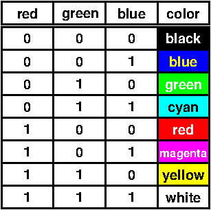
1in the signals_leds) will light up with the color specified by the genericsingleColorValueRGB, where bit 2 of this vector is red, bit 1 green, and bit 0 blue.
Required tcl-script
For both the above mentioned templates, following tcl-script can be used:
set_location_assignment PIN_E21  -to columnAddress[3]
set_location_assignment PIN_E22  -to columnAddress[2]
set_location_assignment PIN_F21  -to columnAddress[1]
set_location_assignment PIN_M22  -to columnAddress[0]

set_location_assignment PIN_F22  -to rowRedLeds_b[0]
set_location_assignment PIN_K19  -to rowRedLeds_b[1]
set_location_assignment PIN_M21  -to rowRedLeds_b[2]
set_location_assignment PIN_P22  -to rowRedLeds_b[3]
set_location_assignment PIN_R22  -to rowRedLeds_b[4]
set_location_assignment PIN_J22  -to rowRedLeds_b[5]
set_location_assignment PIN_U20  -to rowRedLeds_b[6]
set_location_assignment PIN_W22  -to rowRedLeds_b[7]
set_location_assignment PIN_Y22  -to rowRedLeds_b[8]
set_location_assignment PIN_AA21 -to rowRedLeds_b[9]

set_location_assignment PIN_J17  -to rowGreenLeds_b[0]
set_location_assignment PIN_K17  -to rowGreenLeds_b[1]
set_location_assignment PIN_F17  -to rowGreenLeds_b[2]
set_location_assignment PIN_M20  -to rowGreenLeds_b[3]
set_location_assignment PIN_P21  -to rowGreenLeds_b[4]
set_location_assignment PIN_R21  -to rowGreenLeds_b[5]
set_location_assignment PIN_U22  -to rowGreenLeds_b[6]
set_location_assignment PIN_V22  -to rowGreenLeds_b[7]
set_location_assignment PIN_W21  -to rowGreenLeds_b[8]
set_location_assignment PIN_Y21  -to rowGreenLeds_b[9]

set_location_assignment PIN_J18  -to rowBlueLeds_b[0]
set_location_assignment PIN_K18  -to rowBlueLeds_b[1]
set_location_assignment PIN_M19  -to rowBlueLeds_b[2]
set_location_assignment PIN_N20  -to rowBlueLeds_b[3]
set_location_assignment PIN_P20  -to rowBlueLeds_b[4]
set_location_assignment PIN_R20  -to rowBlueLeds_b[5]
set_location_assignment PIN_U21  -to rowBlueLeds_b[6]
set_location_assignment PIN_V21  -to rowBlueLeds_b[7]
set_location_assignment PIN_W20  -to rowBlueLeds_b[8]
set_location_assignment PIN_AA22 -to rowBlueLeds_b[9]

set_location_assignment PIN_B11 -to clock25MHz
set_global_assignment -name SDC_FILE clocks.sdc
with following clocks.sdc file (see for this also the section: clock sources):
set_time_unit ns
set_decimal_places 3
create_clock -period 40.0 -waveform { 0 20.0 } clock25MHz -name contraint1