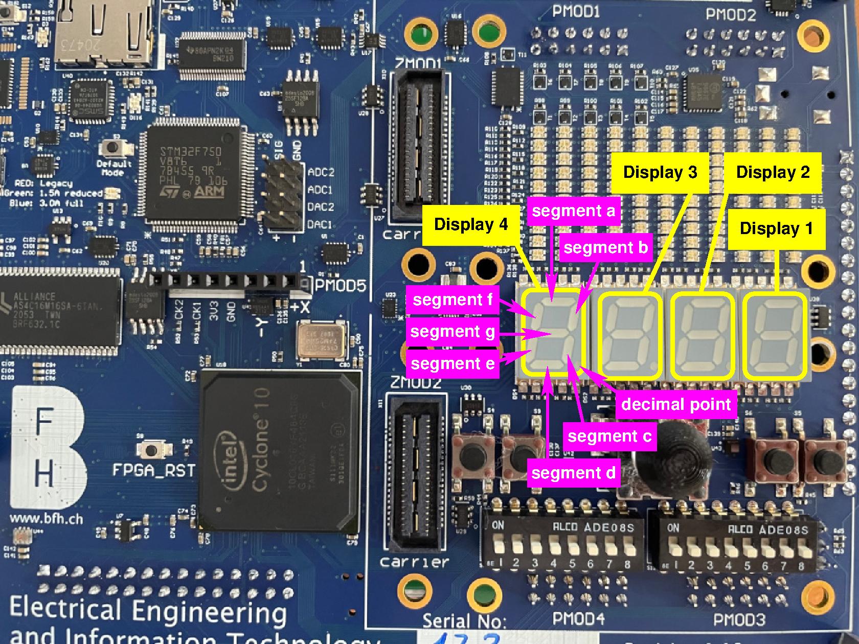
7-Segment displays
The leguan provides four 7-segment displays:
Important
All the segments and the decimal point of each display is active low, meaning that they will light up when a logic level 0 is provided, and that they stay off when a logic level 1 is provided!
The table below shows the pins on which the segments and the decimal point of the displays are connected on the FPGA:
Name: |
Display1: |
Display2: |
Display3: |
Display4: |
|---|---|---|---|---|
segment a |
PIN_L6 |
PIN_P4 |
PIN_N19 |
PIN_T18 |
segment b |
PIN_N7 |
PIN_P6 |
PIN_N16 |
PIN_T17 |
segment c |
PIN_M6 |
PIN_R6 |
PIN_N18 |
PIN_W19 |
segment d |
PIN_M4 |
PIN_J21 |
PIN_P17 |
PIN_Y1 |
segment e |
PIN_N5 |
PIN_T4 |
PIN_R18 |
PIN_Y2 |
segment f |
PIN_M5 |
PIN_R5 |
PIN_N17 |
PIN_H22 |
segment g |
PIN_N6 |
PIN_T5 |
PIN_R19 |
PIN_R17 |
decimal point |
PIN_P7 |
PIN_P5 |
PIN_V4 |
PIN_U19 |
Below you find the snippets on how to use this 7-segments display in your toplevel.
Using the 7-segment display’s
In this section you find a VHDL top-level entity and the corresponding tcl-file that you can use to use the 7-segment display’s.
Important
Although VHDL is case-insensitive, the tcl-files are not. Meaning that the port-names in the top-level entity need to be copied exactly in the tcl-files.
An example for a VHDL top-level entity is shown below:
library ieee;
use ieee.std_logic_1164.all;

entity leguanToplevel is
  port ( display1Segements_b    : out std_logic_vector( 6 downto 0);
         display1DecimalPoint_b : out std_logic);
end leguanToplevel;
To connect the above display to the correct pins of the FPGA, following tcl-script can be used:
set_location_assignment PIN_N6 -to display1Segements_b[6]
set_location_assignment PIN_M5 -to display1Segements_b[5]
set_location_assignment PIN_N5 -to display1Segements_b[4]
set_location_assignment PIN_M4 -to display1Segements_b[3]
set_location_assignment PIN_M6 -to display1Segements_b[2]
set_location_assignment PIN_N7 -to display1Segements_b[1]
set_location_assignment PIN_L6 -to display1Segements_b[0]
set_location_assignment PIN_P7 -to display1DecimalPoint_b
Note
The suffix
_bto the port name. This is general practice to indicate an active-low signal.The LSB of the vector corresponds to segement a and the MSB of the vector corresponds to segment g.
In
VHDLa bit of a vector is selected using round brackets, e.g.display1Segements_b(6). In the tcl-script, however, you have to use square brackets, e.g.display1Segements_b[6].
Hint
To activate the assignments, following steps need to be taken in quartus:
Go to
Tools->Tcl scripts....Add the
tclscript to your project by pressing the ButtonAdd to Project....Highlight the
tclscript by clicking on it in theLibraries:window.Press the
Runbutton.