PMOD connectors
The leguan provides four double-row PMOD interfaces, and one single-row extended PMOD interface. The PMOD specifications can be found here.
PMOD double row interfaces
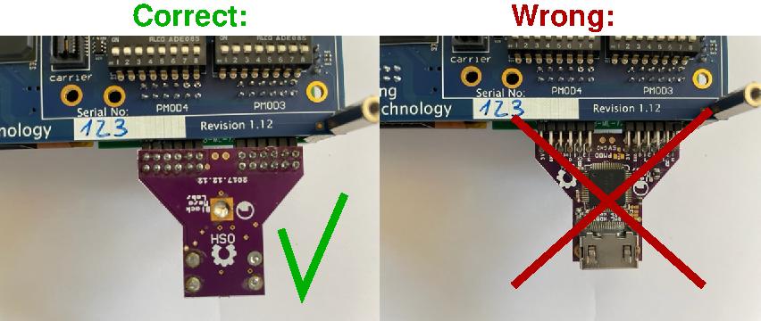
The PMOD double row interfaces are indicated by PMOD1, PMOD2, PMOD3, and PMOD4. They can be used with both single and double-row PMOD-modules. The picture below shows how to correctly insert the modules in the PMOD connectors:
Warning
The PMOD3 interface has, dependent the mode in which the leguan is configured, different functionalities (see also Tools->Analog Discovery 2). If unsure, do not use this interface to connect a PMOD-module!
The functionality of the different pins is shown in the following table:
Pin: |
Function: |
Pin: |
Function: |
|---|---|---|---|
1 |
IO1 |
7 |
IO5 |
2 |
IO2 |
8 |
IO6 |
3 |
IO3 |
9 |
IO7 |
4 |
IO4 |
10 |
IO8 |
5 |
GND |
11 |
GND |
6 |
3.3V |
12 |
3.3V |
PMOD1 interface
The connections of the PMOD1 interface to the FPGA are shown below:
Pin: |
Function: |
FPGA pin: |
Pin: |
Function: |
FPGA pin: |
|---|---|---|---|---|---|
1 |
IO1 |
PIN_E13 |
7 |
IO5 |
PIN_D13 |
2 |
IO2 |
PIN_E14 |
8 |
IO6 |
PIN_F13 |
3 |
IO3 |
PIN_D15 |
9 |
IO7 |
PIN_F14 |
4 |
IO4 |
PIN_F15 |
10 |
IO8 |
PIN_E15 |
PMOD2 interface
The connections of the PMOD2 interface to the FPGA are shown below:
Pin: |
Function: |
FPGA pin: |
Pin: |
Function: |
FPGA pin: |
|---|---|---|---|---|---|
1 |
IO1 |
PIN_B21 |
7 |
IO5 |
PIN_B22 |
2 |
IO2 |
PIN_C20 |
8 |
IO6 |
PIN_C21 |
3 |
IO3 |
PIN_C22 |
9 |
IO7 |
PIN_D20 |
4 |
IO4 |
PIN_D21 |
10 |
IO8 |
PIN_D22 |
PMOD3 interface
The connections of the PMOD3 interface to the FPGA are shown below:
Pin: |
Function: |
FPGA pin: |
Pin: |
Function: |
FPGA pin: |
|---|---|---|---|---|---|
1 |
IO1 |
PIN_E1 |
7 |
IO5 |
PIN_F2 |
2 |
IO2 |
PIN_E4 |
8 |
IO6 |
PIN_E3 |
3 |
IO3 |
PIN_B1 |
9 |
IO7 |
PIN_D2 |
4 |
IO4 |
PIN_C3 |
10 |
IO8 |
PIN_B2 |
PMOD4 interface
The connections of the PMOD4 interface to the FPGA are shown below:
Pin: |
Function: |
FPGA pin: |
Pin: |
Function: |
FPGA pin: |
|---|---|---|---|---|---|
1 |
IO1 |
PIN_J2 |
7 |
IO5 |
PIN_J1 |
2 |
IO2 |
PIN_H1 |
8 |
IO6 |
PIN_J3 |
3 |
IO3 |
PIN_H5 |
9 |
IO7 |
PIN_H2 |
4 |
IO4 |
PIN_F1 |
10 |
IO8 |
PIN_G3 |
PMOD single row extended interface
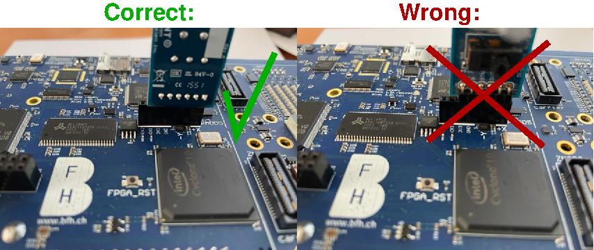
The PMOD single row extended interface is indicated by PMOD5. It can be used for single-row PMOD-modules. The picture below shows how to correctly insert a module in the PMOD connector:
The functionality of the different pins, and their connection to the FPGA, is shown in the following table:
Pin: |
Function: |
FPGA pin: |
|---|---|---|
1 |
IO1 |
PIN_E16 |
2 |
IO2 |
PIN_D17 |
3 |
IO3 |
PIN_B18 |
4 |
IO4 |
PIN_E12 |
5 |
GND |
- |
6 |
3.3V |
- |
7 |
CLK1 |
PIN_B12 |
8 |
CLK2 |
PIN_A12 |
Note
The pins 7 and 8 are not foreseen in the official PMOD specifications. They are added to provide the possibility to connect clock sources to the FPGA (see also FPGA->Clock sources).
Using the PMOD interfaces
In this section you find a VHDL top-level entity and the corresponding tcl-file that you can use to use the PMOD interfaces.
Important
Although VHDL is case-insensitive, the tcl-files are not. Meaning that the port-names in the top-level entity need to be copied exactly in the tcl-files.
An example for a VHDL top-level entity is shown below:
library ieee;
use ieee.std_logic_1164.all;

entity leguanToplevel is
  port ( PMOD5_1     : in  std_logic;
         PMOD5_2     : in  std_logic;
         PMOD5_3     : out std_logic;
         PMOD5_4     : out std_logic);
end leguanToplevel;
To connect the above PMOD interface to the correct pins of the FPGA, following tcl-script can be used:
set_location_assignment PIN_E16 -to PMOD5_1
set_location_assignment PIN_D17 -to PMOD5_2
set_location_assignment PIN_B18 -to PMOD5_3
set_location_assignment PIN_E12 -to PMOD5_4
Hint
To activate the assignments, following steps need to be taken in quartus:
Go to
Tools->Tcl scripts....Add the
tclscript to your project by pressing the ButtonAdd to Project....Highlight the
tclscript by clicking on it in theLibraries:window.Press the
Runbutton.