Analog Discovery 2
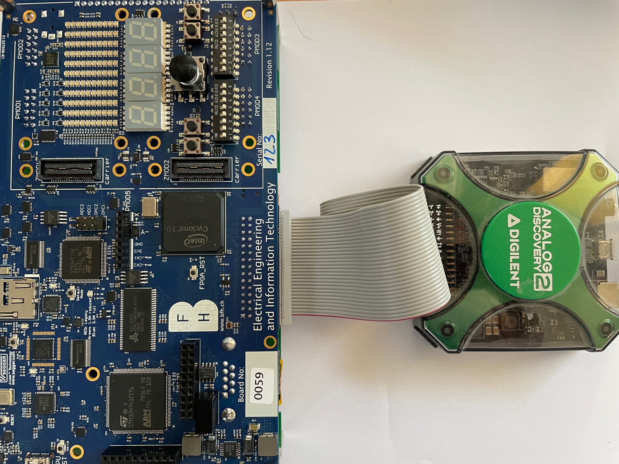
The leguan was designed such that users have the ability to measure/force signals by use of the Digilent Analog Discovery 2. This section describes the different possibilities that can be applied in the different modi of the leguan platform:
Waveforms connections
The analog discovey pins are connected as show in the following table, where it is shown which connections are availabe in a given operating mode of the leguan-platform:
| Waveforms name: | Connection: | Availabe in leguan mode: | Mode: |
|---|---|---|---|
| C1 (scope channel 1) | Audio codec left channel | Any | scope |
| C2 (scope channel 2) | Audio codec right channel | Any | scope |
| DIO0 | Can-bus TxD | CPU and SOC | logic analyzer |
| DIO1 | Can-bus RxD | CPU and SOC | logic analyzer |
| DIO2 | I2C clock | Any | logic analyzer |
| DIO3 | I2C data | Any | logic analyzer |
| DIO4 | I2S MOSI | CPU and SOC | logic analyzer |
| DIO5 | I2S SCK | CPU and SOC | logic analyzer |
| DIO6 | I2S MISO | CPU and SOC | logic analyzer |
| DIO7 | I2S nCS | CPU and SOC | logic analyzer |
| DIO8 | PMOD 3 pin 7 | Mode dependend | logic analyzer/pattern generator |
| DIO9 | PMOD 3 pin 1 | Mode dependend | logic analyzer/pattern generator |
| DIO10 | PMOD 3 pin 8 | Mode dependend | logic analyzer/pattern generator |
| DIO11 | PMOD 3 pin 2 | Mode dependend | logic analyzer/pattern generator |
| DIO12 | PMOD 3 pin 9 | Mode dependend | logic analyzer/pattern generator |
| DIO13 | PMOD 3 pin 3 | Mode dependend | logic analyzer/pattern generator |
| DIO14 | PMOD 3 pin 10 | Mode dependend | logic analyzer/pattern generator |
| DIO15 | PMOD 3 pin 4 | Mode dependend | logic analyzer/pattern generator |
Mode dependend connections
The signals DIO8..DIO15 are mode dependend. This section describes their functionality depending the mode in which the leguan is put.
Important: If you are not sure, do not connect a PMOD module to the PMOD3 connector, as it might damage either the FPGA or the Analog Discovery 2! If you are in menu-modus at start-up, there is no problem, but if your default mode is CPU or SOC there is a risc for damage.
CPU mode
In CPU-mode the DIO8..DIO15 are defined as shown in the table below:
| Waveforms name: | Connection: | Mode: |
|---|---|---|
| DIO8 | Button 4 | logic analyzer |
| DIO9 | 7-segment 1 decimal point | logic analyzer |
| DIO10 | Irq0 or Irq1 | logic analyzer |
| DIO11 | CPU nOE | logic analyzer |
| DIO12 | CPU nWE | logic analyzer |
| DIO13 | CPU nCS | logic analyzer |
| DIO14 | CPU byteEnables LSB | logic analyzer |
| DIO15 | CPU byteEnables MSB | logic analyzer |
SOC mode
In SOC-mode both the User CPU and the FPGA can be programmed. By default, the SOC-mode is equal to the CPU-mode, unless the FPGA is programmed with a custom bitstream, at which it is equal to the FPGA-mode.
FPGA mode
In FPGA mode it is up to the user to define the mode (logic analyser(output) or pattern generator(input)) of each of the signal. This flexibility is put in place with the risc that, when not correctly applied, something may go wrong. Please refer to the description of the PMOD modules in the Board->FPGA->PMOD connectors section.
Conflicts with Quartus Prime Lite
When using the Quartus Prime software to program the FPGA, make sure to disconnect the Analog Discovery 2 from the computer. Intel Quartus Prime has issues detecting the Altera USB Blaster when the Analog Discovery 2 is connected. This is a known issue and currently, this is the best workaround. After the new bitstream has been programmed, the Analog Discovery 2 can be connected again.