Function generator
First, a general overview of the function generator is given. Then the principle of operation is explained before the details of the individual waveforms are explained. In the section after the waveforms, the role of the timers for the function generator is explained. At the end, some limitations and some ideas for future development are listed.
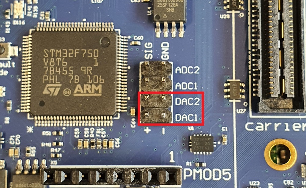
Channel 1 and 2 are availabe on the middle of the dev board, as seen in the image above.
Overview
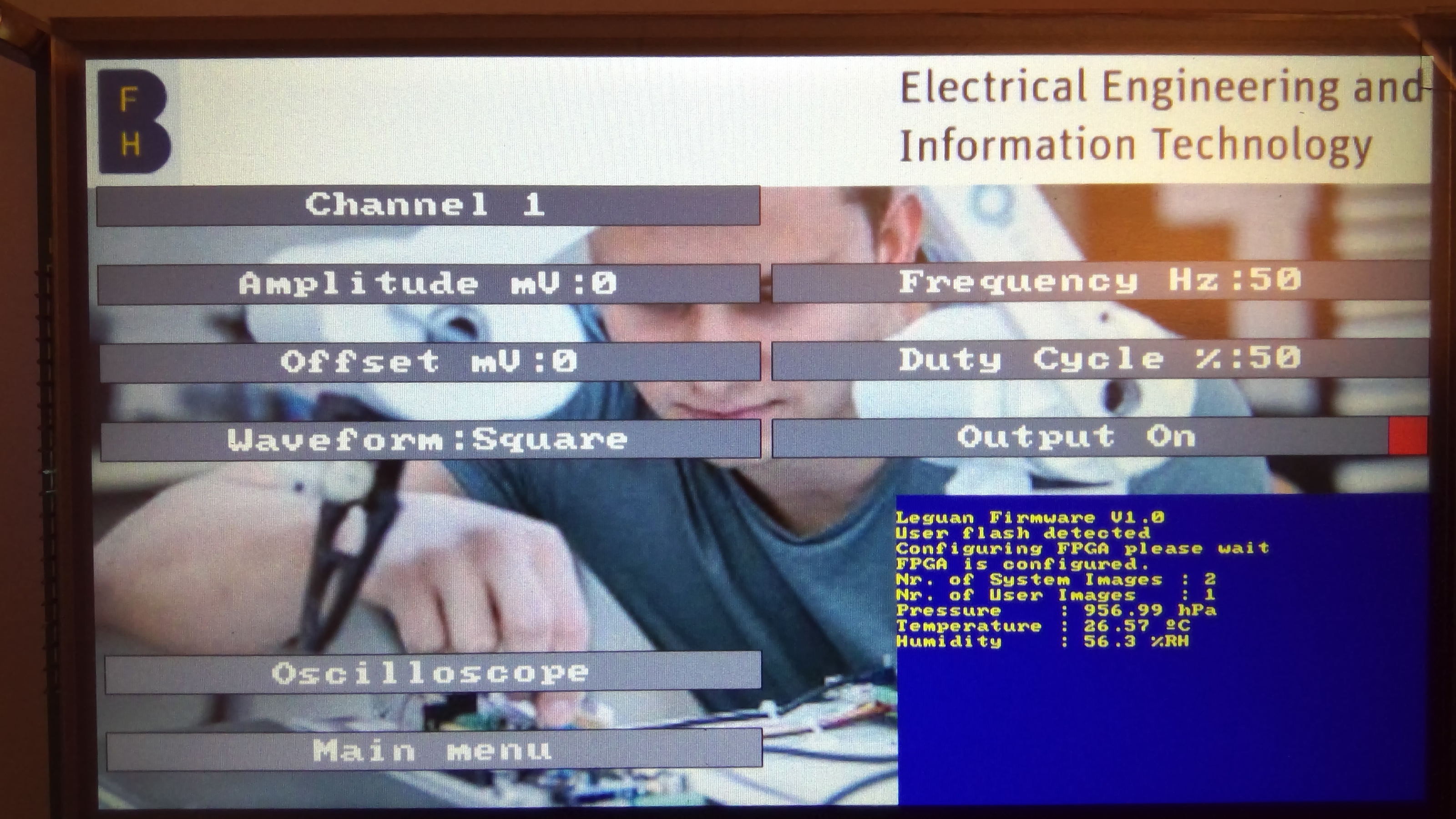
This function generator consists of two channels. Each channel can be adjusted independently. The user can set the parameters with the help of the GUI. The corresponding menu is located in the main menu under the “Waveforms” menu item. The adjustable parameters are:
Amplitude
Frequency
Offset
Duty cycle
Enabling output
Waveform
Some parameters have limits, and all have maximum values. Each parameter that can be set by the user is briefly explained.
The amplitude can only be between a range of 0 and 3300 millivolts. This is because the output voltage of the DAC depends on the reference voltage which is 3.3 volts.
The frequency is limited to 9999 Hz. The limitation is currently due to the numpad used for entering the values (four digits) and the lookup table used to set the frequency of the timer update event. The LUT only provides entries up to a frequency of 1 MHz. However, it must be noted that interrupts are also generated according to the call frequency. For instance, 2 million interrupts per second are currently generated at maximum frequency. This reduces the response time of the system.
The maximum offset is given by the maximum amplitude.
The duty cycle has only an influence on the pulse waveform. It will not affect the other waveforms. Its value corresponds to percentage.
The following waveforms are implemented:
Sine
Pulse (rectangular)
Sawtooth
Triangle
| Parameter | Minimum value | Maximum value |
|---|---|---|
| Amplitude | 0 [mV] | 3’300 [mV] |
| Frequency | 0 [Hz] | 9999 [Hz] |
| Offset | 0 [mV] | 3’300 [mV] |
| Duty cycle | 0 [%] | 100 [%] |
| Enabling Output | 0 | 1 |
Working principle
A main component for the functionality of the function generator is the DACControlStruct. For each channel there is such a structure, in the following it is called DAC channel. The structure consists of the following entries:
Value Buffer
Buffer length
Channel
The value buffer contains all values necessary to render one period of the desired waveform. Consequently, the value buffer defines the appearance of the signal. The Buffer length attribute is equal to the length of the value buffer. The channel attribute corresponds to the DAC channel (either DAC_CHANNEL_1 or DAC_CHANNEL_2).
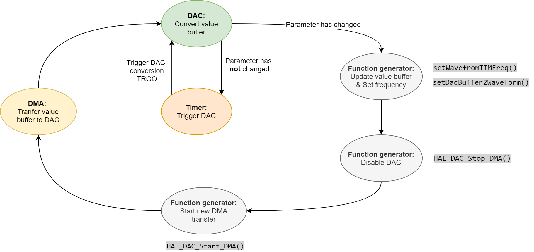
The value buffer is transferred to the DAC by DMA. This is done with the function HAL_DAC_Start_DMA. The DMA is used in circular mode. Circular mode is described as follows in the reference manual (p. 231): “The circular mode is available to handle circular buffers and continuous data flows. When the circular mode is activated, the number of data items to be transferred is automatically reloaded with the initial value programmed during the stream configuration phase, and the DMA requests continue to be served.” This means that the value buffer is transferred again and again, which ensures a continuous representation of the signal. If the waveform changes, the DAC must be deactivated with HAL_DAC_Stop_DMA() before the new waveform can be transferred to the DAC.
The single conversions made by the DAC are triggered by a Timer Trigger Out event (TRGO). This is how the frequency of the signal is controlled. The trigger-out event occurs each time the period of the timer expires. Consequently, the frequency of the timer must be (much) higher than the frequency of the signal.
When a waveform parameter changes, the value buffer is updated. The DAC is then first deactivated before the new buffer is transferred to the DAC.
The following figure shows schematically how the function generator works:
The parameters are stored in funcGenChannel structure. Despite the waveform characteristics such s amplitude or frequency, some auxiliary channel dependant parameters are stored in this structure. This is for example the length of a used LUT, or a step size used for calculations.
Waveforms
As already mentioned, the shape of the signal is given by the content of the DAC channel value buffer. The content of the buffer is calculated every time a parameter has changed. If none of the parameters has changed, the content of the buffer does not change. After the signal buffer was updated it is necessary to clean the data cache (SCB_CleanDCache()). Otherwise, the DMA is transferring old data from RAM to the DAC. By cleaning the data cache, the changed data is written back to the memory.
Besides the content of the value buffer, the ADC call frequency ( timer frequency ) also depends on the waveform. This section explains how the individual waveforms are calculated and how the call frequency is affected by the waveform. The waveforms are calculated in the functions named setDacBuffer2Waveform().
Pulse
The simplest waveform is the pulse waveform. It has either the value of the offset or the value of the sum of amplitude and offset. For the buffer generation of this waveform 100 iterations () are performed. As long as the current iteration is smaller than the duty cycle value (0-100), the value is equal to the sum of amplitude and offset. As soon as the current iteration is greater than the duty cycle, the value is equal to the offset only. The pulse waveform is the only one that depends on the duty cycle. This waveform always needs a buffer length of 100. The call frequency is always 100 times greater than the actual signal frequency.
| Attribute | Value |
|---|---|
| Buffer length | |
| Call frequency |
Sine
The sine calculation is based on two normalized lookup tables (LUT), which are stored in the header file “SineLUTComplete.h”. There are two different sizes of the LUT, because a compromise between resolution and call frequency has to be made. The shorter LUT has a length of 100 and the larger one has 200 entries. Consequently, the shorter LUT is used for higher frequencies and the longer one for lower frequencies. The length is chosen by multiplying the frequency by the length of the long LUT. If the result is greater than the maximum allowed call frequency, the short LUT is selected.
The length of the LUT also determines the length of the buffer. The LUTs are stored in a fixed-point representation (Q16.16).
Both LUTs are normalized to one. To obtain the correct waveform, the amplitude is multiplied by each LUT entry. Please note, since a fixed-point representation (Q16.16) is used for the LUT, fixed point multiplication (MULT_16_16()) must be used.
At the end, the offset must be added to the value stored in the buffer.
| Attribute | Value |
|---|---|
| Buffer length | LUT Length ( |
| Call frequency | LUT Length |
Sawtooth
The generation of this waveform is done in two steps. This is due to the conflict between resolution and call frequency. First, the step size for incrementing the values is determined. For this purpose, a small step size is assumed. Then the theoretical call frequency for this step size is compared with the largest allowed call frequency. If this criterion is not met, the step size is increased, and the result is compared again. This process is repeated until a step size is found so that the calling frequency is lower than the maximum calling frequency. This is done in a separate function(setSawToothTIMFreq()). The call frequency is also set in this function.
Once the step size has been determined, the waveform can be calculated. To do this, the number of iterations must be calculated by dividing the amplitude by the step size. The initial value corresponds to the offset. Then the entries can be calculated by adding the step size to the previous value. This is done for the number of iterations calculated.
Note that there is a relationship between the amplitude, the step size and the call frequency. If, for example, the amplitude increases while the step size remains the same, more entries would be required in the value buffer, leading to a higher call frequency.
There is a possible mismatch between the selected amplitude and the calculated result because the step size is never equal to one. However, the error is minimized by selecting the smallest step size that matches the maximum call frequency criterion.
| Attribute | Value |
|---|---|
| Buffer length | |
| Call frequency |
Triangle
As one can imagine, the calculation for the triangular waveform is very similar to the calculation for the sawtooth waveform.
Again, the step size must first be calculated. Compared to the sawtooth waveform, twice as many calls are required to obtain the same frequency with the same step size and amplitude for a triangular waveform. However, since the maximum call frequency is limited, the step size is in most cases larger than that of the sawtooth waveform. The step size is determined as described in the sawtooth waveform section, but the call frequency is twice as high for the same parameters. The timer frequency is set in this step (setTriangleTIMFreq()).
The values of the waveform are also calculated very similarly as before. But the number of iterations is also doubled. As long as the number of the current iteration is smaller than half of the total iterations, the step size is added to the previous value. After that, the step size is subtracted from the previous value.
For the triangle waveform there exists a link between amplitude, step size and calling frequency too.
| Attribute | Value |
|---|---|
| Buffer length | |
| Call frequency | |
| Step size |
Timer
As mentioned before, the trigger output (TRGO) of the timer is used to trigger the DAC and is thus responsible for the correct frequency of the signal. This function can be activated in the IOC file by selecting the Timer X Trigger Out event in the Trigger menu. Or by setting the DAC_Trigger entry in the DAC_ChannelConfTypeDef before configuring the DAC.
To set the frequency, there are two different 16-bit registers that must be set. The prescaler (PSC) and the auto reload register (ARR). The value stored in the prescaler register divides the clock of the timer. The timer counts from zero to the value stored in the ARR register. The update event is generated when the counter value is equal to the value stored in the ARR. This event also activates the trigger output. The counter is then reset to zero and the cycle starts again. Thus, the period depends on the values stored in the PSC and ARR registers. Reference manual, p. 862–874
Both registers (ARR and PSC) can be changed by software, which is done by calling the setPSCARR() function to achieve the correct call frequency.
The frequency of the TRGO can be calculated as follows:
Known Issues and limitations
Output stuck after parameter change
Sometimes after a parameter change, the output gets stuck at a certain level. This happens more often at higher frequencies. The reason for this behavior is not known. Sometimes a DMA underrun error (p. 466) occurred, but not every time this error was encountered. However, when switching the output off and back on again the waveform is generated as desired.
Frequency
The biggest limitation regarding the parameters is the frequency.
Currently the lookup table (PSCARRLUT) is the limiting factor. It only has entries up to a frequency of 1 MHz. However, it already consumes a lot of memory with its 19,900 entries. It would be interesting to test the system for its actual maximum frequency.
It should be noted that as the frequency increases, so does the number of interrupts generated by the timer. At a certain point, this will block the entire system. Currently, the maximum call frequency for each channel is set to 1 MHz, which corresponds to 2 million interrupts per second, if both channels are running at the maximum calling frequency.
Look out
As mentioned earlier, it would be interesting to create a larger lookup table for the PSC and ARR values and test the system for its maximum tolerable frequency.
There is also the possibility of implementing more waveforms, such as noise. Or to make the waveforms more parametrisable.
File overview
The following table gives an overview and a short description of the files which are relevant for the function generator.
| File | Content |
|---|---|
| FunctionGenerator/functionGenerator.h | Contains all macros, typedefs and function declerations concerning the function generator. |
| FunctionGenerator/functionGenerator.c | Implementation of the functions. |
| FunctionGenerator/PSCARRLUT.h | Lookup table (LUT) for setting prescaler and automatic reload register of the timers. |
| FunctionGenerator/SineLUTComplete.h | Two different LUTs of different sizes (100, 200). Both LUTs contain one period of a sine wave normalised to one. Note: Fixed point representation is Q0.16 |
| gui/funcGenMenu.h | Declaration of global accessible GUI functions |
| gui/funcGenMenu.c | Implementation of menu handling functions |
Source code documentation
Structures
-
struct DACControlStruct
Structure for controlling the DAC.
Public Members
-
uint32_t valueBuffer[DACBUFLENGTH]
Buffer containing the data for the DMA transfer, aka the waveform displayed next.
-
uint32_t Channel
Either DAC_CHANNEL_1 or DAC_CHANNEL_2, defined in hal_dac.h.
-
uint16_t bufferLength
Amount of data points to be transferred to the DAC. Dependent on Wavelength.
-
uint32_t valueBuffer[DACBUFLENGTH]
-
struct funcGenAdjustmentHandler
Structure for handling the adjustment of the function generator parameters.
- See
funcGenChannel
Public Members
-
enum chToAdjust numChannelToAdjust
Enum indicating the current channel selected.
-
enum paramToAdjust parameterToAdjust
Enum indicating the current parameter to be adjusted.
-
struct funcGenChannel *funcGenChannelToAdjust
Reference to the selected funbction generator channel.
-
uint32_t maxValue
Maximum value which can be set.
-
struct funcGenChannel
Structure which holds the Function Generator parameters for one channel.
Public Members
-
uint16_t frequency
Waveform frequency.
-
uint16_t amplitude
-
uint16_t offset
-
uint16_t dutyCycle
Currently only used for Pulse waveform */.
-
uint32_t channel
Either DAC_CHANNEL_1 or DAC_CHANNEL_2, defined in hal_dac.h.
-
uint8_t lengthLUT
Length of the LUT, used because two different LUT’s used for Sine waveform.
-
uint8_t outputOn
Output enabled or not.
-
uint8_t stepSize
Size of the step, added to the previous value. Used only for Triangle and Sawtooth waveform.
-
uint16_t frequency
functionGenerator.h
This file holds the decleration of the functions, the enums and typedefs used for the function generator functionality.
@date Sep 21, 2020
- Author
bmm1
- See
funcGenAdjustmentHandler
- See
osciAdjustmentHandler
- Version
0.1: 22.04.2021 First cleaned up version
Defines
-
MAXDACVAL
Maximum value of DAC (12 Bit)
-
DACBUFLENGTH
DAC Buffer Length, used for one DMA transfer, currently maximum length is used for triangle and sawtooth waveform and is obtained by calculating: amplitude/stepSize. setTriangleTIMFreq() setSawToothTIMFreq.
-
MINFREQUENCY
-
MAXFREQUENCY
-
MAXAMPLITUDE
-
MAXOFFSET
-
MAXDUTYCYCLE
-
MAXOUTPUTON
-
MAXCALLFREQ
Maximum timer frequency.
Typedefs
-
typedef enum paramToAdjust paramToAdjust
Enum for handling the function generator parameter to be adjusted.
- See
funcGenAdjustmentHandler
-
typedef struct funcGenChannel funcGenChannel
Structure which holds the Function Generator parameters for one channel.
-
typedef struct funcGenAdjustmentHandler funcGenAdjustmentHandler
Structure for handling the adjustment of the function generator parameters.
- See
funcGenChannel
Enums
-
enum chToAdjust
Enum for handling the channel to be adjusted.
- See
funcGenAdjustmentHandler
Values:
-
enumerator NONE
-
enumerator CH1
-
enumerator CH2
-
enum paramToAdjust
Enum for handling the function generator parameter to be adjusted.
- See
funcGenAdjustmentHandler
Values:
-
enumerator FREQUENCY
-
enumerator AMPLITUDE
-
enumerator OFFSET
-
enumerator DUTY_CYCLE
-
enumerator OUTPUT_ON
-
enumerator CHANNEL
-
enumerator WAVE_FORM
-
enumerator NONE_SELECTED
-
enumerator EXIT
Functions
-
void initDACConrolStruct(void)
Initialising DAC control structure.
Called from the function generator intialisation function
- See
initFuncGen() DACControlStruct
-
void initFuncGen(void)
Initialise the function generator.
Initialising the function generator channel structures. Output is disabled by default for both channels. Additionally PSC and ARR register of the Timer are set.- See
funcGenChannel setPSCARR()
-
void switchOutputOnOff(uint32_t Channel, uint8_t switchOn)
Switch DACs and timers according to channel on or off.
- Parameters
Channel – DAC channel to switch on or off
switchOn – State to switch to (0 or 1)
0: Off
1: On
-
void setDACNewValue(uint32_t channel, uint16_t newValue)
-
void kickoff_DAC(uint32_t *buf, uint16_t length, funcGenAdjustmentHandler *funcGenHandler)
Start DAC DMA stream after changing function generator parameters.
The values from the buffer are copied into the value buffer of the DAC channel structure. Afterwards if the output is on and the amplitude is greater than zero, a new DMA stream is started to the corresponding DAC channel.- See
funcGenAdjustmentHandler, HAL_DAC_Start_DMA()
- Parameters
uint32_t – *buf: Buffer containing the values to be streamed to the DAC
uint16_t – length: Buffer length
funcGenAdjustmentHandler – *funcGenHandler: Reference to the Adjustment handler
-
void setDacBuffer2Triangle(funcGenAdjustmentHandler *funcGenHandler)
Calculate the DAC buffer for triangle wave from.
This function is only called, when either the amplitude, the offset or the waveform has changed. It will recalculate a period of the waveform and trigger a new DMA stream to the corresponding DAC channel. Afterwards the buffer within the DACControlStruct structure is used to send data to the DAC. There are two phases in the calculation, the rising and the falling phase. As long the rising phase is active, the new value (n+1) in the buffer is stepSize greater than the previous value (n). As soon have of the period is over (nCycles), the falling phase starts. Now the new value is stepSize smaller then the previous one. The stepSize is calculated dynamically. This is necessary to restrict the buffer size to a size, which is in accordance with the MAXCALLFREQ. The stepSize is calculated in the setTriangleTIMFreq() function. There is a conflict between resolution and maximum frequency.- See
DACControlStruct, setTriangleTIMFreq()
- Parameters
funcGenAdjustmentHandler – *funcGenHandler: The function generator adjustment handler, of which the waveform will be adjusted
-
void setDacBuffer2Pulse(funcGenAdjustmentHandler *funcGenHandler)
Calculate the DAC buffer for pulse wave from.
This function is only called, when either the amplitude, the offset or the waveform has changed. It will recalculate a period of the waveform and trigger a new DMA stream to the corresponding DAC channel. Afterwards the buffer within the DACControlStruct structure is used to send data to the DAC. The value is either equal to the amplitude or the offset. As long the counting variable is smaller than the duty cycle the value is equal to the amplitude, if the counting variable is greater than the duty cycle, the value is equal to the offset.- See
DACControlStruct
- Parameters
funcGenAdjustmentHandler – *funcGenHandler: The function generator adjustment handler, of which the waveform will be adjusted
-
void setDacBuffer2Sawtooth(funcGenAdjustmentHandler *funcGenHandler)
Calculate the DAC buffer for sawtooth wave from.
This function is only called, when either the amplitude, the offset or the waveform has changed. It will recalculate a period of the waveform and trigger a new DMA stream to the corresponding DAC channel. Afterwards the buffer within the DACControlStruct structure is used to send data to the DAC. The new value is equal to the value incremented by the step. Is this made nCycles times. which is calculated by dividing the amplitude by the step. The step is calculated dynamically. This is necessary to restrict the buffer size to a size, which is in accordance with the MAXCALLFREQ. At the same time the smallest possible step is taken to have the best possible resolution. The step is calculated in the setSawtoothTIMFreq() function. There is a conflict between resolution and maximum frequency.- See
DACControlStruct, setSawtoothTIMFreq()
- Parameters
funcGenAdjustmentHandler – *funcGenHandler: The function generator adjustment handler, of which the waveform will be adjusted
-
void setDacBuffer2Sine(funcGenAdjustmentHandler *funcGenHandler)
Calculate the DAC buffer for sawtooth wave from.
This function is only called, when either the amplitude, the offset or the waveform has changed. It will recalculate a period of the waveform and trigger a new DMA stream to the corresponding DAC channel. Afterwards the buffer within the DACControlStruct structure is used to send data to the DAC. A normalized lookup table (LUT) is used for calculating the sine wave. The LUT is defined in the SIneLUTComplete.h header and the values are stored in 16 Bit. There are two different tables a longer (200) and a shorter (100) one.It is checked, if for the selected frequency we can take the longer LUT or if we have to choose the shorter one (MAXCALLFREQ). The amplitude is multiplied by the value of the LUT, here Q16.16 fixed point multiplication is used. The final result is obtained by adding the offset. At the end the PSC and ARR register of the corresponding Timer are set to obtain the correct call frequency.- See
DACControlStruct, MAXCALLFREQ, MULT16_16()
- Parameters
funcGenAdjustmentHandler – *funcGenHandler: The function generator adjustment handler, of which the waveform will be adjusted
-
void setPSCARR(unsigned int, unsigned int channel)
Set the frequency of the timer, which generates the trigger for the DC.
The values for the PSC (Prescaler) and ARR (Auto reload register) are stored in a LUT (PSCARRLUT.h). The frequencies the values correspond to are not stored in the LUT, because this would consume 15 % of the Flash capacity at the current size of the LUT. Therefore there is a algorithm built in in this function which follows the same scheme as the LUT was made. Until a certain frequency (limitX) we have a corresponding step Size (stepSizeX). The index of the LUT is then calculated with the help of this parameters. Afterwards the registers (PSC & ARR) of the corresponding timer are adapted.- Attention
If you adapt the LUT this function needs to be adapted to!
- See
PSCARRLUT
- Parameters
freq – Frequency to set
channel – Function generator channel
-
void setSawToothTIMFreq(funcGenAdjustmentHandler *funcGenHandler)
Set the frequency for Sawtooth wave from.
Calculates the calling frequency for this waveform and the selected frequency. The calling frequency is the trigger for the DAC and realised with timers. Additionally the stepSize is calculated, since its maximum value depends on the frequency.- See
-
void setTriangleTIMFreq(funcGenAdjustmentHandler *funcGenHandler)
Set the frequency for Triangle wave from.
Calculates the calling frequency for this waveform and the selected frequency. The calling frequency is the trigger for the DAC and realised with timers. Additionally the stepSize is calculated, since its maximum value depends on the frequency.- See
-
void funcGenSetAmp(uint8_t channel, uint16_t amp)
Setter function for the amplitude of the desired channel. Used from GUI so parameter changes are taking effect. Value is checked, before it takes effect.
- Parameters
channel – Either enum CH1 or CH2
amp – Value must be between 0 and MAXAMPLITUDE
-
void funcGenSetFreq(uint8_t channel, uint16_t freq)
Setter function for the frequency of the desired channel. Used from GUI so parameter changes are taking effect. Value is checked, before it takes effect.
- Parameters
channel – Either enum CH1 or CH2
freq – value must be between MINFREQUENCY and MAXFREQUENCY
-
void funcGenSetOffset(uint8_t channel, uint16_t offset)
Setter function for the offset of the desired channel. Used from GUI so parameter changes are taking effect. Value is checked, before it takes effect.
- Parameters
channel – Either enum CH1 or CH2
offset – value must be between 0 and MAXOFFSET
-
void funcGenSetDutyCycle(uint8_t channel, uint16_t dutyCycle)
Setter function for the output state (On or Off) of the desired channel. Used from GUI so parameter changes are taking effect. Value is checked, before it takes effect.
- Parameters
channel – Either enum CH1 or CH2
dutyCycle – value must be between 0 and MAXDUTYCYCLE
-
void funcGenSetOutputOn(uint8_t channel, bool state)
Setter function for the output state (On or Off) of the desired channel. Used from GUI so parameter changes are taking effect.
- Parameters
channel – Either enum CH1 or CH2
state – On (true) or Off (false)
-
void funcGenSetWaveform(uint8_t channel, uint8_t waveform)
-
uint16_t getAmp(uint8_t channel)
Getter function for the Amplitude of the desired channel. Used in GUI to display the value.
- Parameters
channel – Either enum CH1 or CH2
-
uint16_t getFreq(uint8_t channel)
Getter function for the frequency of the desired channel. Used in GUI to display the value.
- Parameters
channel – Either enum CH1 or CH2
-
uint16_t getOffset(uint8_t channel)
Getter function for the offset of the desired channel. Used in GUI to display the value.
- Parameters
channel – Either enum CH1 or CH2
-
uint16_t getDutyCycle(uint8_t channel)
Getter function for the duty cycle of the desired channel. Used in GUI to display the value.
- Parameters
channel – Either enum CH1 or CH2
-
uint16_t getOutputOn(uint8_t channel)
Getter function for the output state (On or Off) of the desired channel. Used in GUI to display the value.
- Parameters
channel – Either enum CH1 or CH2
- Returns
0 – Off
1 – On
-
uint8_t getEWaveform(uint8_t channel)
Getter function for the waveform of the desired channel. Used in GUI to display the value.
- Parameters
channel – Either enum CH1 or CH2
-
bool funcGenEvaluateNumParam(int value, paramToAdjust param)
Checks if a parameter entered is within the allowed range.
Variables
-
DACControlStruct DACChannel1
DAC Control structure for channel 1.
-
DACControlStruct DACChannel2
DAC Control structure for channel 2.
-
funcGenChannel funcGenCH1
Function generator control structure for channel 1.
-
funcGenChannel funcGenCH2
Function generator control structure for channel 2.
-
struct DACControlStruct
- #include <functionGenerator.h>
Structure for controlling the DAC.
Public Members
-
uint32_t valueBuffer[DACBUFLENGTH]
Buffer containing the data for the DMA transfer, aka the waveform displayed next.
-
uint32_t Channel
Either DAC_CHANNEL_1 or DAC_CHANNEL_2, defined in hal_dac.h.
-
uint16_t bufferLength
Amount of data points to be transferred to the DAC. Dependent on Wavelength.
-
uint32_t valueBuffer[DACBUFLENGTH]
-
struct funcGenChannel
- #include <functionGenerator.h>
Structure which holds the Function Generator parameters for one channel.
Public Members
-
uint16_t frequency
Waveform frequency.
-
uint16_t amplitude
-
uint16_t offset
-
uint16_t dutyCycle
Currently only used for Pulse waveform */.
-
uint32_t channel
Either DAC_CHANNEL_1 or DAC_CHANNEL_2, defined in hal_dac.h.
-
uint8_t lengthLUT
Length of the LUT, used because two different LUT’s used for Sine waveform.
-
uint8_t outputOn
Output enabled or not.
-
uint8_t stepSize
Size of the step, added to the previous value. Used only for Triangle and Sawtooth waveform.
-
WaveForms waveForm
Currently selected waveform.
-
uint16_t frequency
-
struct funcGenAdjustmentHandler
- #include <functionGenerator.h>
Structure for handling the adjustment of the function generator parameters.
- See
funcGenChannel
Public Members
-
enum chToAdjust numChannelToAdjust
Enum indicating the current channel selected.
-
enum paramToAdjust parameterToAdjust
Enum indicating the current parameter to be adjusted.
-
struct funcGenChannel *funcGenChannelToAdjust
Reference to the selected funbction generator channel.
-
uint32_t maxValue
Maximum value which can be set.
functionGenerator.c
This file holds the implementations of the functions used for the function generator functionality.
@date Sep 21, 2020
- Author
bmm1
- Version
0.1: 22.04.2021 First cleaned up version 0.2: 19.07.2021 Added D$-cleaning when updating signal
Functions
-
void initDACConrolStruct()
Initialising DAC control structure.
Called from the function generator intialisation function
- See
initFuncGen() DACControlStruct
-
void initFuncGen()
Initialise the function generator.
Initialising the function generator channel structures. Output is disabled by default for both channels. Additionally PSC and ARR register of the Timer are set.- See
funcGenChannel setPSCARR()
-
void switchOutputOnOff(uint32_t Channel, uint8_t switchOn)
Switch DACs and timers according to channel on or off.
- Parameters
Channel – DAC channel to switch on or off
switchOn – State to switch to (0 or 1)
0: Off
1: On
-
void kickoff_DAC(uint32_t *buf, uint16_t length, funcGenAdjustmentHandler *funcGenHandler)
Start DAC DMA stream after changing function generator parameters.
The values from the buffer are copied into the value buffer of the DAC channel structure. Afterwards if the output is on and the amplitude is greater than zero, a new DMA stream is started to the corresponding DAC channel.- See
funcGenAdjustmentHandler, HAL_DAC_Start_DMA()
- Parameters
uint32_t – *buf: Buffer containing the values to be streamed to the DAC
uint16_t – length: Buffer length
funcGenAdjustmentHandler – *funcGenHandler: Reference to the Adjustment handler
-
void setDacBuffer2Triangle(funcGenAdjustmentHandler *funcGenHandler)
Calculate the DAC buffer for triangle wave from.
This function is only called, when either the amplitude, the offset or the waveform has changed. It will recalculate a period of the waveform and trigger a new DMA stream to the corresponding DAC channel. Afterwards the buffer within the DACControlStruct structure is used to send data to the DAC. There are two phases in the calculation, the rising and the falling phase. As long the rising phase is active, the new value (n+1) in the buffer is stepSize greater than the previous value (n). As soon have of the period is over (nCycles), the falling phase starts. Now the new value is stepSize smaller then the previous one. The stepSize is calculated dynamically. This is necessary to restrict the buffer size to a size, which is in accordance with the MAXCALLFREQ. The stepSize is calculated in the setTriangleTIMFreq() function. There is a conflict between resolution and maximum frequency.- See
DACControlStruct, setTriangleTIMFreq()
- Parameters
funcGenAdjustmentHandler – *funcGenHandler: The function generator adjustment handler, of which the waveform will be adjusted
-
void setDacBuffer2Pulse(funcGenAdjustmentHandler *funcGenHandler)
Calculate the DAC buffer for pulse wave from.
This function is only called, when either the amplitude, the offset or the waveform has changed. It will recalculate a period of the waveform and trigger a new DMA stream to the corresponding DAC channel. Afterwards the buffer within the DACControlStruct structure is used to send data to the DAC. The value is either equal to the amplitude or the offset. As long the counting variable is smaller than the duty cycle the value is equal to the amplitude, if the counting variable is greater than the duty cycle, the value is equal to the offset.- See
DACControlStruct
- Parameters
funcGenAdjustmentHandler – *funcGenHandler: The function generator adjustment handler, of which the waveform will be adjusted
-
void setDacBuffer2Sawtooth(funcGenAdjustmentHandler *funcGenHandler)
Calculate the DAC buffer for sawtooth wave from.
This function is only called, when either the amplitude, the offset or the waveform has changed. It will recalculate a period of the waveform and trigger a new DMA stream to the corresponding DAC channel. Afterwards the buffer within the DACControlStruct structure is used to send data to the DAC. The new value is equal to the value incremented by the step. Is this made nCycles times. which is calculated by dividing the amplitude by the step. The step is calculated dynamically. This is necessary to restrict the buffer size to a size, which is in accordance with the MAXCALLFREQ. At the same time the smallest possible step is taken to have the best possible resolution. The step is calculated in the setSawtoothTIMFreq() function. There is a conflict between resolution and maximum frequency.- See
DACControlStruct, setSawtoothTIMFreq()
- Parameters
funcGenAdjustmentHandler – *funcGenHandler: The function generator adjustment handler, of which the waveform will be adjusted
-
void setDacBuffer2Sine(funcGenAdjustmentHandler *funcGenHandler)
Calculate the DAC buffer for sawtooth wave from.
This function is only called, when either the amplitude, the offset or the waveform has changed. It will recalculate a period of the waveform and trigger a new DMA stream to the corresponding DAC channel. Afterwards the buffer within the DACControlStruct structure is used to send data to the DAC. A normalized lookup table (LUT) is used for calculating the sine wave. The LUT is defined in the SIneLUTComplete.h header and the values are stored in 16 Bit. There are two different tables a longer (200) and a shorter (100) one.It is checked, if for the selected frequency we can take the longer LUT or if we have to choose the shorter one (MAXCALLFREQ). The amplitude is multiplied by the value of the LUT, here Q16.16 fixed point multiplication is used. The final result is obtained by adding the offset. At the end the PSC and ARR register of the corresponding Timer are set to obtain the correct call frequency.- See
DACControlStruct, MAXCALLFREQ, MULT16_16()
- Parameters
funcGenAdjustmentHandler – *funcGenHandler: The function generator adjustment handler, of which the waveform will be adjusted
-
void setPSCARR(unsigned int freq, unsigned int channel)
Set the frequency of the timer, which generates the trigger for the DC.
The values for the PSC (Prescaler) and ARR (Auto reload register) are stored in a LUT (PSCARRLUT.h). The frequencies the values correspond to are not stored in the LUT, because this would consume 15 % of the Flash capacity at the current size of the LUT. Therefore there is a algorithm built in in this function which follows the same scheme as the LUT was made. Until a certain frequency (limitX) we have a corresponding step Size (stepSizeX). The index of the LUT is then calculated with the help of this parameters. Afterwards the registers (PSC & ARR) of the corresponding timer are adapted.- Attention
If you adapt the LUT this function needs to be adapted to!
- See
PSCARRLUT
- Parameters
freq – Frequency to set
channel – Function generator channel
-
void setSawToothTIMFreq(funcGenAdjustmentHandler *funcGenHandler)
Set the frequency for Sawtooth wave from.
Calculates the calling frequency for this waveform and the selected frequency. The calling frequency is the trigger for the DAC and realised with timers. Additionally the stepSize is calculated, since its maximum value depends on the frequency.- See
-
void setTriangleTIMFreq(funcGenAdjustmentHandler *funcGenHandler)
Set the frequency for Triangle wave from.
Calculates the calling frequency for this waveform and the selected frequency. The calling frequency is the trigger for the DAC and realised with timers. Additionally the stepSize is calculated, since its maximum value depends on the frequency.- See
-
void updateSignal(funcGenChannel *channel)
Updates the signal of the function generator.
This function updates the DAC buffer by calling the corresponding update function. In addition, the frequency of the corresponding timer is updated too, if needed. This function is called, every time a parameter gets adjusted in the GUI. After the buffer was updated the data cache must be cleaned. This ensures, that the changed data is written back to the memory. This procedure is needed, so the DMA transfers the adjusted data to the DAC.- See
setPSCARR(), SCB_CleanDCache()
- Parameters
channel – Pointer to the channel which was changed.
-
bool funcGenEvaluateNumParam(int value, paramToAdjust param)
Checks if a parameter entered is within the allowed range.
-
uint16_t getAmp(uint8_t channel)
Getter function for the Amplitude of the desired channel. Used in GUI to display the value.
- Parameters
channel – Either enum CH1 or CH2
-
void funcGenSetAmp(uint8_t channel, uint16_t amp)
Setter function for the amplitude of the desired channel. Used from GUI so parameter changes are taking effect. Value is checked, before it takes effect.
- Parameters
channel – Either enum CH1 or CH2
amp – Value must be between 0 and MAXAMPLITUDE
-
uint16_t getFreq(uint8_t channel)
Getter function for the frequency of the desired channel. Used in GUI to display the value.
- Parameters
channel – Either enum CH1 or CH2
-
void funcGenSetFreq(uint8_t channel, uint16_t freq)
Setter function for the frequency of the desired channel. Used from GUI so parameter changes are taking effect. Value is checked, before it takes effect.
- Parameters
channel – Either enum CH1 or CH2
freq – value must be between MINFREQUENCY and MAXFREQUENCY
-
void funcGenSetWaveform(uint8_t channel, WaveForms waveform)
Setter function for the waveform of the desired channel. Used from GUI so parameter changes are taking effect.
- Parameters
channel – Either enum CH1 or CH2
waveform – value must be of type WaveForms
-
uint16_t getOffset(uint8_t channel)
Getter function for the offset of the desired channel. Used in GUI to display the value.
- Parameters
channel – Either enum CH1 or CH2
-
uint8_t getEWaveform(uint8_t channel)
Getter function for the waveform of the desired channel. Used in GUI to display the value.
- Parameters
channel – Either enum CH1 or CH2
-
void funcGenSetOffset(uint8_t channel, uint16_t offset)
Setter function for the offset of the desired channel. Used from GUI so parameter changes are taking effect. Value is checked, before it takes effect.
- Parameters
channel – Either enum CH1 or CH2
offset – value must be between 0 and MAXOFFSET
-
uint16_t getDutyCycle(uint8_t channel)
Getter function for the duty cycle of the desired channel. Used in GUI to display the value.
- Parameters
channel – Either enum CH1 or CH2
-
void funcGenSetDutyCycle(uint8_t channel, uint16_t dutyCycle)
Setter function for the output state (On or Off) of the desired channel. Used from GUI so parameter changes are taking effect. Value is checked, before it takes effect.
- Parameters
channel – Either enum CH1 or CH2
dutyCycle – value must be between 0 and MAXDUTYCYCLE
-
uint16_t getOutputOn(uint8_t channel)
Getter function for the output state (On or Off) of the desired channel. Used in GUI to display the value.
- Parameters
channel – Either enum CH1 or CH2
- Returns
0 – Off
1 – On
-
void funcGenSetOutputOn(uint8_t channel, bool state)
Setter function for the output state (On or Off) of the desired channel. Used from GUI so parameter changes are taking effect.
- Parameters
channel – Either enum CH1 or CH2
state – On (true) or Off (false)
Variables
-
DAC_HandleTypeDef hdac
DAC Handler.
-
UART_HandleTypeDef huart1
UART handler, UART1 used for user interaction.
-
TIM_HandleTypeDef htim6
Timer handler, timer 6 used as trigger for channel 1 DAC.
-
TIM_HandleTypeDef htim7
Timer handler, timer 7 used as trigger for channel 2 DAC.
-
DACControlStruct DACChannel1
DAC Control structure for channel 1.
-
DACControlStruct DACChannel2
DAC Control structure for channel 2.
-
funcGenChannel funcGenCH1
Function generator control structure for channel 1.
-
funcGenChannel funcGenCH2
Function generator control structure for channel 2.
-
funcGenAdjustmentHandler adjustHandler
TODO: This structure is actually obsolete, but multiple functions are affected if this structure gets removed.